
Welcome to CivilGEO Knowledge Base
Welcome to CivilGEO Knowledge Base
The Simplify Elements command allows the user to simplify the selected polylines or polygons boundary by identifying and removing unnecessary vertices, ultimately reducing feature complexity while retaining inherent character and shape.
Follow the steps below to use the Simplify Elements command:
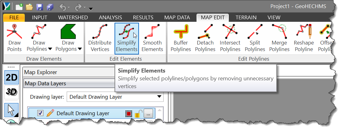
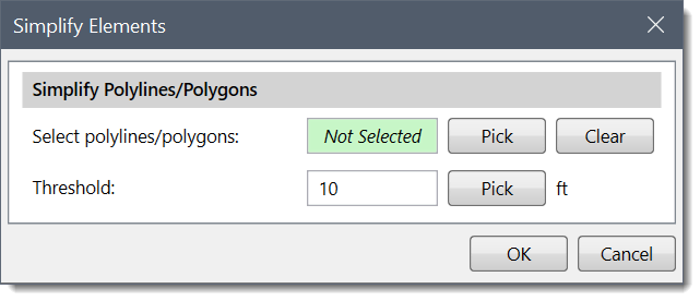
The following section describes how to use the Simplify Elements command and interact with the above dialog box.
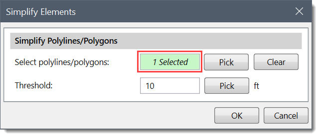
This section is used to manually select polylines or polygons from the Map View. Click the [Pick] button adjacent to the Select polylines/polygons entry. The Simplify Elements dialog box will temporarily disappear, and a prompt will be displayed on the status bar directing the user on what to do next. The user can then select the polylines or polygons from the Map View. Once finished, press the [Enter] key or right-click and select Done from the displayed context menu. The Simplify Elements dialog box will be redisplayed. The total number of selected polylines or polygons will be displayed in the Select polylines/polygons entry.
The user can click the [Clear] button to deselect the selected polylines or polygons and redo the entire process.
Note that the user can also preselect the polylines or polygons from the Map View prior to running this command. If the polylines or polygons were preselected on the Map View, the number of selected polylines will be displayed in the Select polylines/polygons entry.
The value in the Threshold entry field represents the degree of vertex displacement relative to adjacent vertices. By default, the software uses a value of 10 ft. The user can enter a different value or use the [Pick] button to measure the threshold value from the Map View. A larger threshold value results in fewer vertices defining the polyline or polygon.
The software uses the Douglas-Peucker algorithm to reduce the number of redundant vertices that define polylines and polygons, thereby simplifying the geometry. An illustration of how the Douglas-Peucker algorithm iteratively simplifies a polyline is shown below.
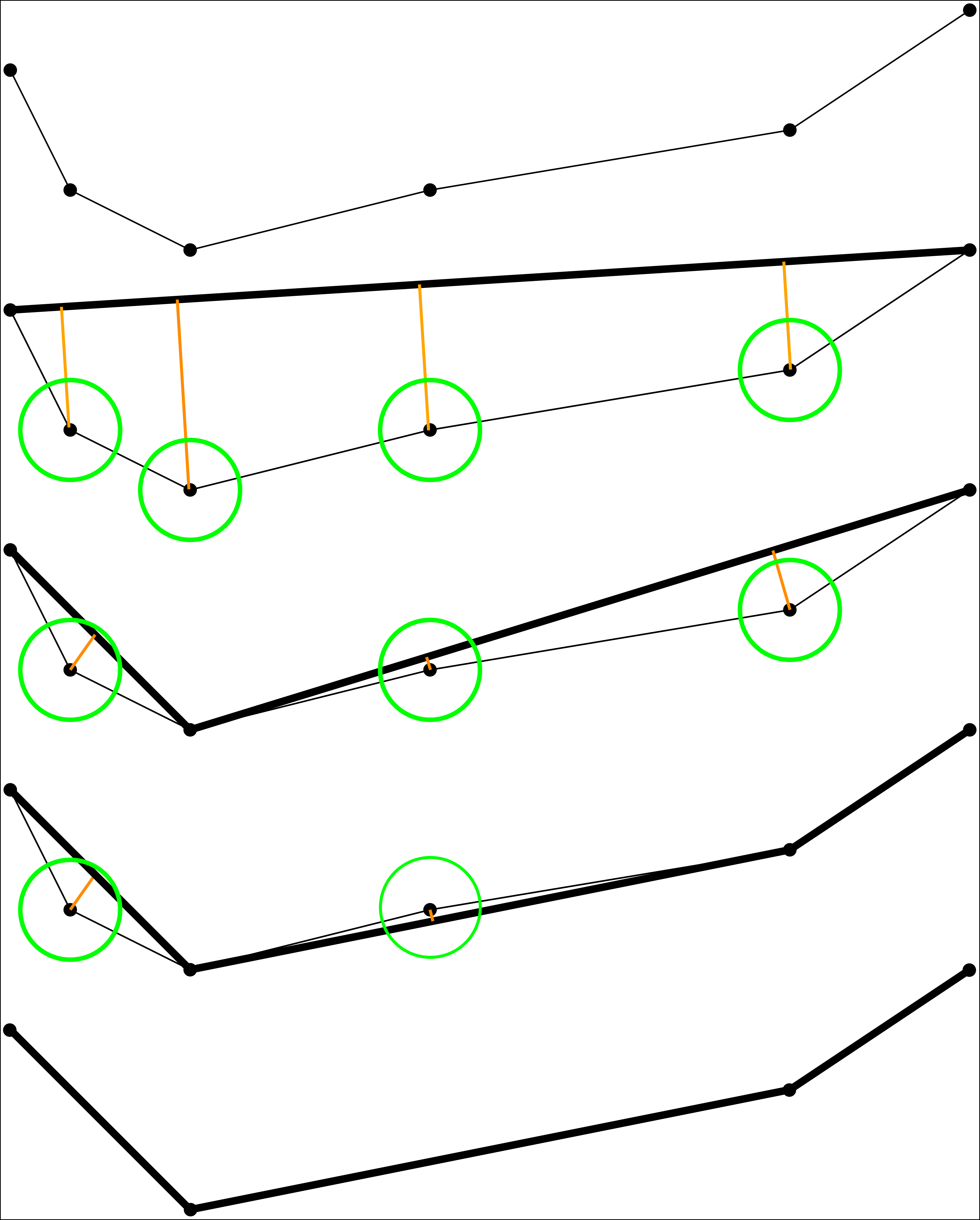
The threshold value is depicted as the radius of the green circle. Critical vertices are first identified, which define the representative shape of the element. Then, redundant vertices are discarded.
A reasonable starting threshold value would be 10 feet (3 meters). This value can be increased to remove additional vertices. Engineering judgment should be used when deciding on a final value.
When the data has been defined in the Simplify Elements dialog box, click the [OK] button. Internally, the software will simplify the polyline or polygon boundary by reducing the number of redundant vertices used to describe the polyline or polygon, while preserving its essential shape.


CivilGEO G2 Reviews
4.8/5.0 Rating, Over 230 Reviews

GeoHECRAS is recognized as the top Civil Engineering Design Software with an average of 4.8 out of 5.0 rating from over 230 real user reviews on G2.


We use cookies to give you the best online experience. By agreeing you accept the use of cookies in accordance with our cookie policy.
When you visit any web site, it may store or retrieve information on your browser, mostly in the form of cookies. Control your personal Cookie Services here.


