The River Channel Modification command allows the user to define a trapezoidal cut into the existing channel geometry or create a new channel geometry. In order to perform a channel modification analysis, a hydraulic model of the existing river reach is required. Once the model is complete, channel modifications can be made to perform trapezoidal cuts and fill into the existing geometry. The user can see a profile view of the channel modification along the river, and can either draw the channel bottom, define a channel bottom slope to use, or instruct the software to interpolate the channel bottom between selected cross sections. In addition, the user can specify that the channel modification follow along the existing river centerline or select a new alignment polyline to use—for example, when performing stream channel restoration back to a sinuous river path.
After the changes have been added to the river channel, a HEC-RAS analysis can be performed to see what effect these changes have on the computed water surface elevation, depth of flow, velocity, and shear stress. This command can be used when performing stable channel design and for fish waterway and passage design.
Follow the steps below to use the River Channel Modification command:
- From the Input ribbon menu, click the Cross Sections menu item, and then select the River Channel Modification command.
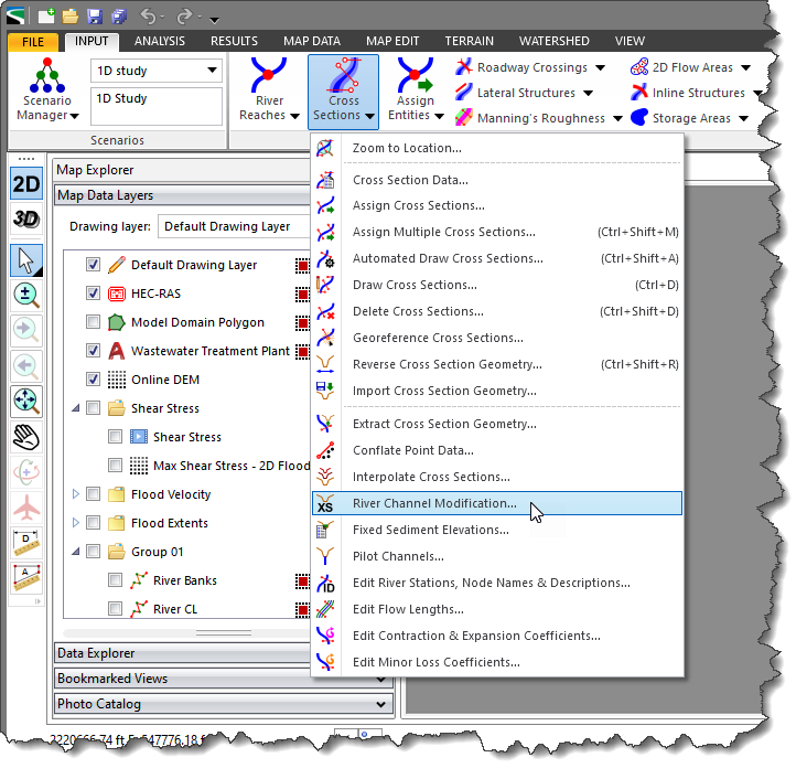
- The River Channel Modification dialog box will be displayed.
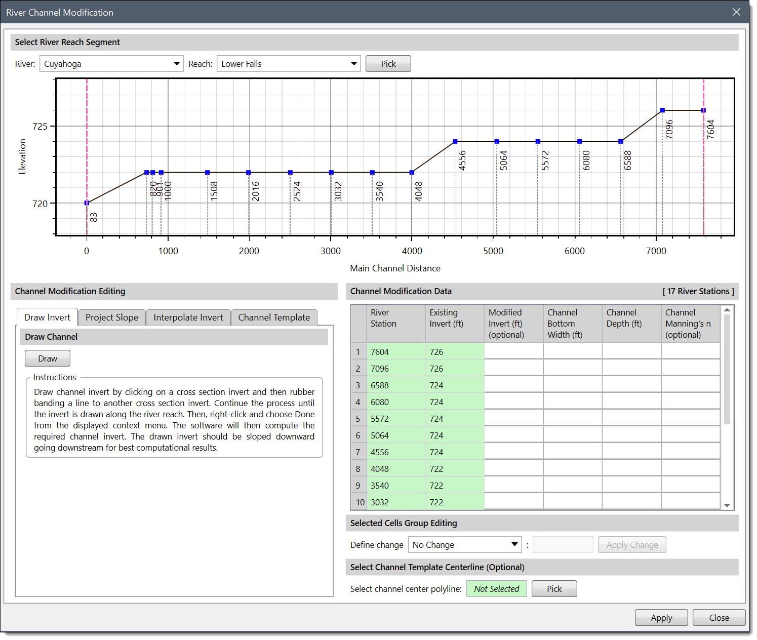
The following sections describe how to interact with the above dialog box.
Selecting River Reach Segment
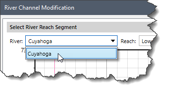
This section is used to define the river and the reach for performing channel modifications. Follow these steps:
- Click on the River dropdown combo box and then select the river for performing channel modifications.
- If there are multiple reaches for the selected river, click on the Reach dropdown combo box and then select the reach for performing channel modifications.
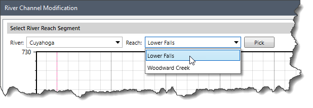
Alternatively, click on the [Pick] button and the River Channel Modification dialog box will temporarily disappear. The software will then prompt the user to select the river reach from the Map View. After selecting a river reach, the River Channel Modification dialog box will redisplay with the river reach shown as selected.
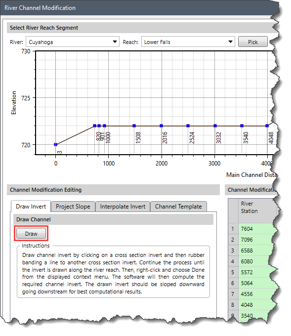
In addition, a graphical plotting is provided that displays a longitudinal view of the river reach and the modified river reach.
Channel Modification Editing
This section allows parameters to be defined for performing channel modifications and for creating a new channel template. This includes the modification method and respective parameters for defining channel inverts over a range of cross sections as well as the parameters to define a trapezoidal cut for the selected cross sections. The following optional tabs are available:
- Draw Invert: This section allows for the drawing of channel inverts (channel bottom) along the existing river reach. Click the [Draw] button, and then draw channel inverts on the graphical plot available under the Select River Reach Segment section. Then, right-click and select Done from the displayed context menu. The software will then compute the required channel invert.
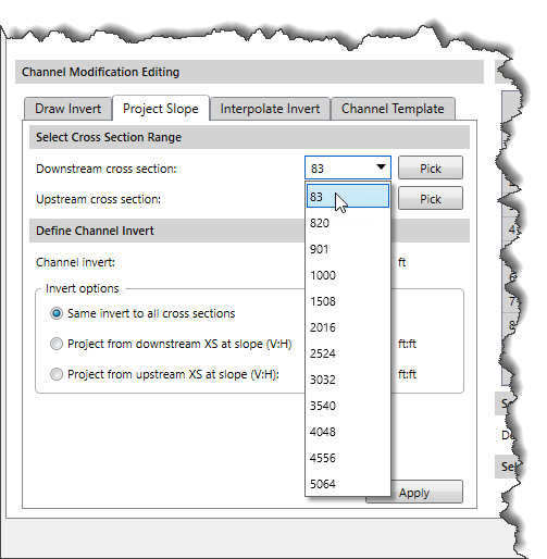
- Project Slope: This section allows the user to define a new channel bottom slope using one of the following methods:
- Specific invert elevations can be defined for each of the cross sections in the selected cross section range.
- The user can enter an elevation for the most downstream cross section and request that the invert elevations for the other cross sections be computed by projecting cuts on a constant slope upstream.
- The elevation entered can be applied to the most upstream cross section of the range, and all others will be computed by projecting a user specified slope downstream.
Follow the steps below to define a new channel bottom slope:
-
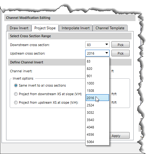
- Click the Downstream cross section dropdown combo box and then select the cross section that will be used as the downstream most river station for applying channel invert.
- Click the Upstream cross section dropdown combo box and then select the cross section that will be used as the upstream most river station for applying channel invert.
- Define the Channel invert elevation.
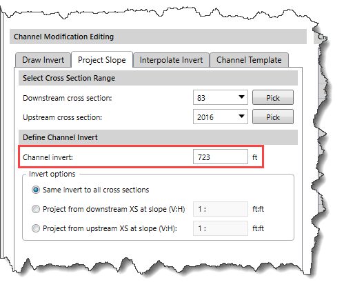
- In the Invert options section, select the desired option for applying the invert elevation for each of the cross sections within the selected range.
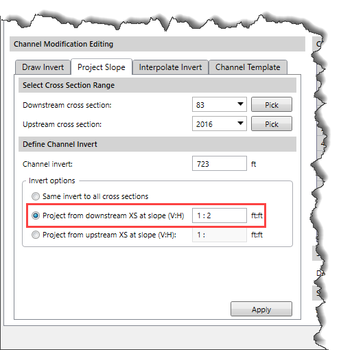
- Click the [Apply] button.
-
- Click the Downstream cross section dropdown combo box and then select the cross section that will be used as the downstream most river station for applying channel invert.
- Click the Upstream cross section dropdown combo box and then select the cross section that will be used as the upstream most river station for applying channel invert.
- Define the Downstream XS channel invert elevation and the Upstream XS channel invert elevation.
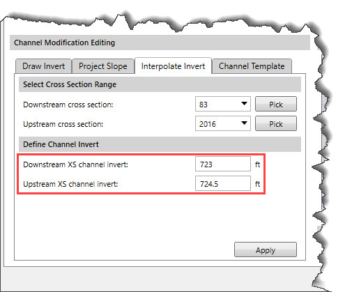
- Click the [Apply] button.
-
- Click the Downstream cross section dropdown combo box and then select the cross section that will be used as the downstream most river station for applying channel modification.
- Click the Upstream cross section dropdown combo box and then select the cross section that will be used as the upstream most river station for applying channel modification.
- Specify Channel bottom width to represent the bottom width of the trapezoidal cuts.
- Specify Channel Manning’s n value to represent the new Manning’s n value to be applied to each of the trapezoidal cuts.
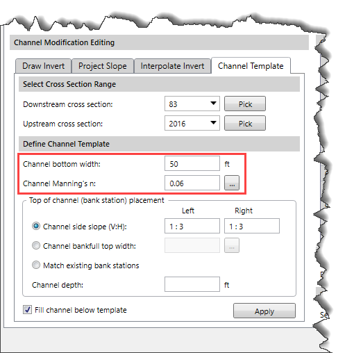
- In the Top of channel (bank station) placement section, select one of the following radio button options:
- Channel side slope (V:H): This option allows defining a vertical versus horizontal channel side slope for both the left and the right riverbank stations.
- Channel bankfull top width: This option sets the left and right bank stations at a distance equal to the channel bankfull top width. The user can simply enter the channel bankfull top width or click the […] button and interactively measure the bankfull top width from the map view.
- Match existing bank stations: This option automatically places the modified bank stations exactly at the spots where existing channel bank stations lie.
- Enter the Channel depth value.
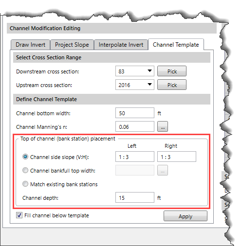
- By default, the Fill channel below template checkbox option is checked. If checked, the option will fill the main channel of the cross section before applying the channel template.
- After the options for channel modification have been defined, click the [Apply] button and the software will create a new modified channel geometry.
Channel Modification Data
This section contains a table that displays a summary of all modifications that will be made to the selected river reach when the new geometry is created. Any update in the modification data is automatically reflected in the table.
Selected Cells Group Editing
This section allows for rapid enter/edit of the channel modification data in the modification summary table (described above).
Follow the steps below to update the channel modification data:
- Select desired cells in the channel modification table.
- Click the Define change dropdown combo box and then select one of the options for updating the cells value and enter the change coefficient. The following options are available:
- Add Constant: This option adds a constant value to the selected cells value.
- Multiply By Factor: This option multiples a user-defined number to the selected cells value.
- Apply Value: This option replaces the selected cells value with the user-specified value.
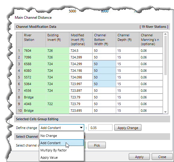
- Click the [Apply Change] button.
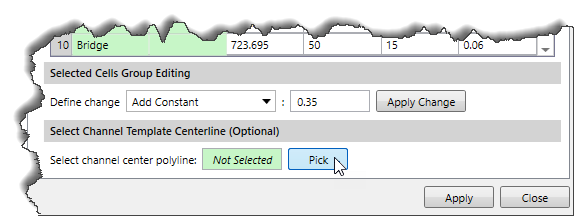
Selected Channel Template Centerline (Optional)
By default, the channel modifications are applied based on the existing river centerline. However, this section allows the user to interactively select a new alignment polyline to use for channel modification. This option is useful when performing stream channel restoration back to a sinuous, pre-channelized path. Click on the [Pick] button adjacent to the Select channel center polyline entry and select the new alignment polyline from the Map View.
After the options for channel modification have been defined, click the [Apply] button, and the software will create a new modified channel geometry.


