Reaches define the elements (i.e., pipes, ditches, streams, etc.) that route flows through the stormwater network model. In GeoHECHMS, the Reach Data command allows the user to add new reach and edit reach data in a project.
Follow the steps below to view or modify the reach data:
From the Input ribbon menu, select the Reach Data command. Alternatively, the user can either double-click on the reach polyline from the Map View or choose the Reach Data command from the Routing Reaches dropdown menu of the Input ribbon menu.
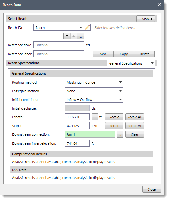
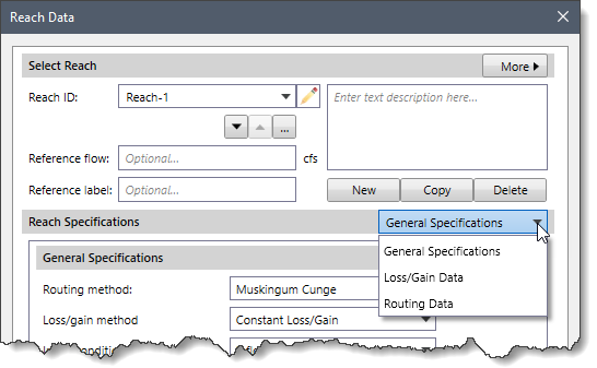
The Reach Data dialog box will be displayed.
The following sections describe the Reach Data command and how to interact with the above dialog box.
Selecting Reach
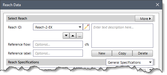
This section allows the user to select the reach in order to define the reach data. The user can create a new reach, copy existing reach data to a new reach, and delete a reach. In addition, the user can navigate between reaches and enter a description detailing the defined reach.
The following options are provided in this section:
Reach ID
This dropdown combo box lists all the reaches that are defined in the model. The user can select the desired reach from the dropdown combo box. Click the pencil icon to edit the reach ID.
The user can navigate between the previous and next reaches using the up and down arrow buttons. Alternatively, the user can click the […] button to select the reach from the Map View.
Note that the up and down arrow buttons will be disabled (i.e., grayed out) when the model contains only a single reach.
Description
This text field allows the user to enter additional information that describes the selected reach.
New
The [New] button allows the user to create a new reach. On clicking this button, the dialog box will temporarily disappear. A prompt will be displayed on the status bar informing the user to draw the reach in an upstream to downstream direction on the Map View. Once finished, press the [Enter] key, or right-click and select Done from the displayed context menu. While drawing a reach, the user can press the [Esc] key to abort the creation of a new reach and return the dialog box to its previous state.
The dialog box will be redisplayed. Next, enter the reach name in the Reach ID entry and click the [Accept changes] button. The software checks that the defined ID is unique. If not, a warning dialog box is displayed, and the user is then returned to the Reach ID field to change the ID.
Copy
The [Copy] button allows the user to copy existing reach data to a new reach. When this command is executed, the software automatically provides a unique default name for the duplicated reach. The cursor is then placed into the Reach ID. The user can go with the default name or enter a different valid and unique ID before moving on to add any other data.
Delete
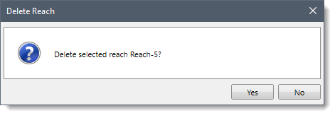
The [Delete] button allows the user to delete the current reach data from the model. Clicking the [Delete] button causes the following confirmational dialog box to be displayed. Click the [Yes] button to delete the selected reach data.
Click the [No] button to abort the deletion process.
Reach Specifications
The following sections describe the reach. Click on the dropdown selector at the Reach Specifications entry to display the various data panels that define the reach data.
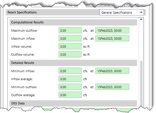
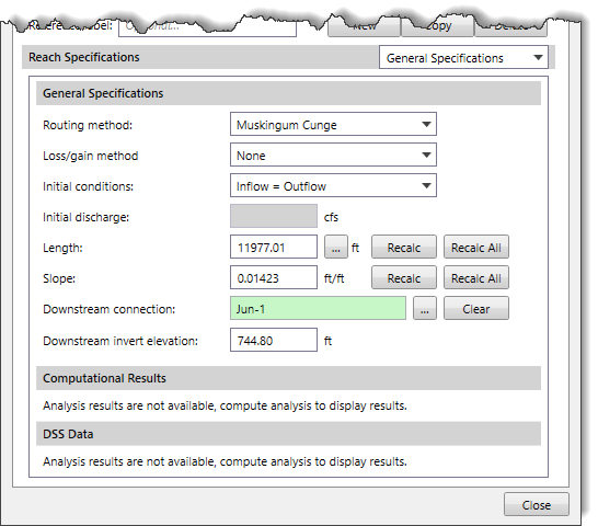
General Specifications
This panel allows the user to define the routing and loss/gain methods to be used for the current reach.
Note that the routing and loss/gain methods are defined for the project in the Scenario Manager and will be displayed automatically in the corresponding dropdown entries. However, the user can change the desired method for the selected reach from this dialog box. Refer to this article in our knowledge base to learn how to use the Scenario Manager dialog box.
The following options are provided in this data panel:
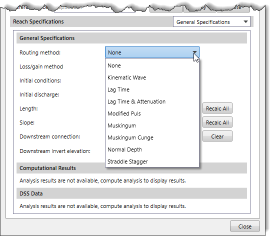
Routing method
This dropdown combo box allows the user to select the routing method for the selected reach. While a reach element conceptually represents a segment of stream or river, the actual calculations are performed by a routing method contained within the reach. The dropdown combo box provides the following routing methods.
None
Kinematic Wave
Lag Time
Lag Time & Attenuation
Modified Puls
Muskingum
Muskingum Cunge
Normal Depth
Straddle Stagger
Refer to this article in our knowledge base to learn about various HEC-HMS routing methods.
Loss/gain method
This dropdown combo box allows the user to select the loss/gain method for the selected reach. While a reach element conceptually represents a segment of stream or river, optional modeling of interactions with the subsurface is performed by a loss/gain method contained within the reach. The dropdown combo box provides the following loss/gain methods.
None
Constant Loss/Gain
Percolation Loss
Refer to this article in our knowledge base to learn about various HEC-HMS loss/gain methods.
Initial conditions
This dropdown combo box entry sets the amount of stored water in the storage area at the start of the simulation. The dropdown combo box lists the following conditions:
Discharge
Inflow = Outflow
If you use the first option, you will also have to enter a discharge value. If you use the second option, it will be assumed that the initial outflow is the same as the initial inflow to the reach from upstream elements. This is essentially the same as assuming a steady-state initial condition.
Initial discharge
This entry field defines the initial discharge being released from the storage area. This entry is only available when the Initial conditions entry has been set to the Discharge option. Otherwise, this entry is disabled (i.e., grayed out).
Length
This entry field defines the length of the selected reach. The user can either enter the value manually or click the […] button to measure the length from the Map View. Clicking on the […] button allows the user to draw a measurement polyline representing the flow length of the selected reach. However, initially the software will assign the length from the defined reach polyline. If the user graphically edits the reach polyline, then the length value automatically updates based upon the Recompute dimensions on element edits checkbox setting in the Options backstage page. Refer to this article in our knowledge base to learn about the Options backstage page.
Clicking on the [Recalc] button causes the software to automatically update this field value with the corresponding digitized reach polyline length. Similarly, the [Recalc All] button causes the software to update the lengths for all digitized reach polylines.
Note that this entry is disabled (i.e., grayed out) for the following routing methods: Lag Time, Lag Time & Attenuation, Modified Puls, Muskingum, and Straddle Stagger.
Slope
This entry field defines the slope of the selected reach. The software will automatically compute the slope based upon the connected element elevations (where possible). However, the user can override the assigned slope by manually defining the value. If the connected elements’ invert elevations change, then the software automatically updates this value based upon the Recompute dimensions on element edits checkbox setting in the Options backstage page. Refer to this article in our knowledge base to learn about the Options backstage page.
Clicking on the [Recalc] button causes the software to automatically update this field value with the corresponding slope based upon changed elevations. Similarly, the [Recalc All] button causes the software to update the slopes for all reaches.
Note that this entry is disabled (i.e., grayed out) for the following routing methods: Lag Time, Lag Time & Attenuation, Modified Puls, Muskingum, and Straddle Stagger.
Downstream connection
This entry field defines the downstream element that the selected reach drains to. Clicking on the […] button allows the user to select the downstream element from the Map View. The following elements can be selected.
Diversion
Junction
Reach
Reservoir
Sink
Note that a reach can connect downstream to another reach. Multiple reaches can be chained together to represent a long river reach with changing geometry. However, a reach cannot connect downstream to a subbasin.
Downstream invert elevation
This entry field defines the invert elevation at the downstream end of the selected reach.
If the selected reach is not connected to another reach (i.e., connected to a junction, etc.), then this field is read-only, showing the invert elevation of the connected element.
If the selected reach is connected to another reach, then this field is editable. The software will attempt to compute this value by using the upstream invert elevation (if available) and the defined reach length and slope values. The user can also override the computed invert elevation by manually defining the value.
Note that this entry is disabled (i.e., grayed out) for the following routing methods: Lag Time, Lag Time & Attenuation, Muskingum, and Straddle Stagger.
Computational Results
This section allows the user to see the analysis results for the current reach that was computed by HEC-HMS.
Note that the Detailed Results section provides additional analysis results for the current reach that was computed by HEC-HMS.
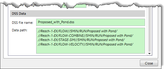
DSS Data
This section includes an external DSS file for referencing HEC-HMS computational results. It allows the user to easily copy the references and paste them into GeoHECRAS.
DSS file name: This entry defines the external DSS file to be used for reading the data.
Data path: This entry denotes the data path within the DSS data file, which contains the paired data.
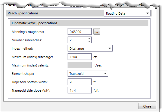
Routing Data
The Routing Data panel is used to enter the data for the selected routing method for the defined reaches. This panel is displayed when the Routing Data option is selected in the Reach Specifications dropdown combo box. Note that the Routing Data panel content changes based upon the routing method selected in the General Specifications section.
Refer to this article in our knowledge base to learn more about this panel.
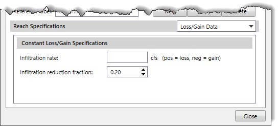
Loss/Gain Data
The Loss/Gain Data panel is used to enter data for the selected loss/gain method for the defined reaches. This panel is displayed when the Loss/Gain Data option is selected in the Reach Specifications dropdown combo box. Note that the Loss/Gain Data panel content changes based upon the loss/gain method selected in the General Specifications section.
Refer to this article in our knowledge base to learn more about this panel.
When you visit any web site, it may store or retrieve information on your browser, mostly in the form of cookies. Control your personal Cookie Services here.
For perfomance reasons we use Cloudflare as a CDN network. This saves a cookie "__cfduid" to apply security settings on a per-client basis. This cookie is strictly necessary for Cloudflare's security features and cannot be turned off.
__cfduid
Preference cookies enable a website to remember information that changes the way the website behaves or looks, like your preferred language or the region that you are in.
For purposes of marketing, optimization of products and services, we use services of ZoomInfo on this website.
The ZoomInfo WebSights snippet drops three cookies to track Unique Visits:
1. _pxhd - Related to the Perimeter X security layer (Perimeter X isused to prevent bot attacks).
2. _cfduid - Related to the CloudFlare security layer (CloudFlare is the Network Security protocol that ZoomInfo uses to orchestrate the rate limiting rules).
3. visitorId - This is how WebSights identifies recurring visitors

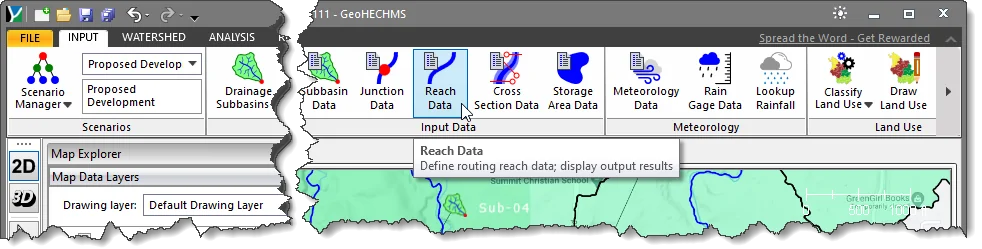 Alternatively, the user can either double-click on the reach polyline from the Map View or choose the Reach Data command from the Routing Reaches dropdown menu of the Input ribbon menu.
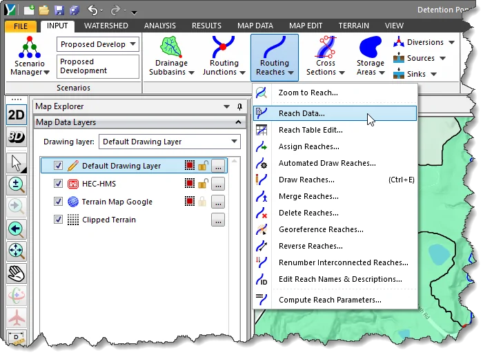
![[Accept changes] button](/wp-content/uploads/sites/25/2023/04/Reach-Data-Image-5.png)
 Click the [Yes] button to delete the selected reach data.
 Refer to this article in our knowledge base to learn about various HEC-HMS routing methods.
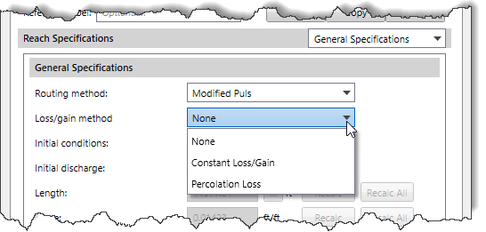 Refer to this article in our knowledge base to learn about various HEC-HMS loss/gain methods.
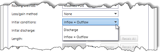 If you use the first option, you will also have to enter a discharge value. If you use the second option, it will be assumed that the initial outflow is the same as the initial inflow to the reach from upstream elements. This is essentially the same as assuming a steady-state initial condition.