
Welcome to CivilGEO Knowledge Base
Welcome to CivilGEO Knowledge Base
The Pilot Channels command allows the user to define a pilot channel along the river reach. Pilot channels are used for unsteady flow modeling. In order to stabilize unsteady flow models, placing a thin pilot channel along the river reach helps the model to converge to a stable solution. A pilot channel acts as a cushion of water during the computations, greatly speeding up the unsteady flow computations. The user can graphically adjust the pilot channel in the river profile view, selecting the region to apply the pilot channel cut along the river reach. This is helpful when the channel bottom is highly irregular along the river reach. Creating a uniform pilot channel slope along the river reach tends to dampen out the effects of the channel bottom irregularities.
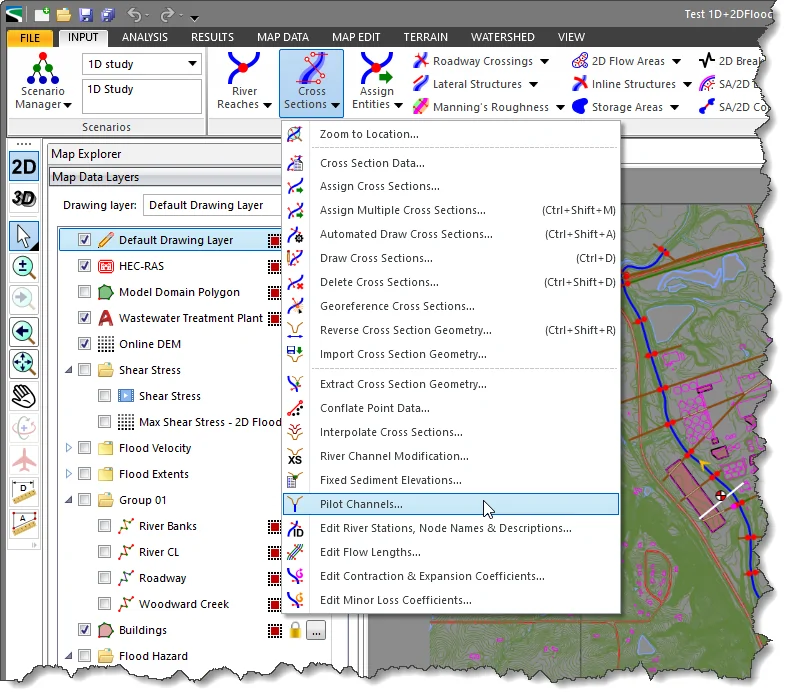
Follow the steps below to use the Pilot Channels command:
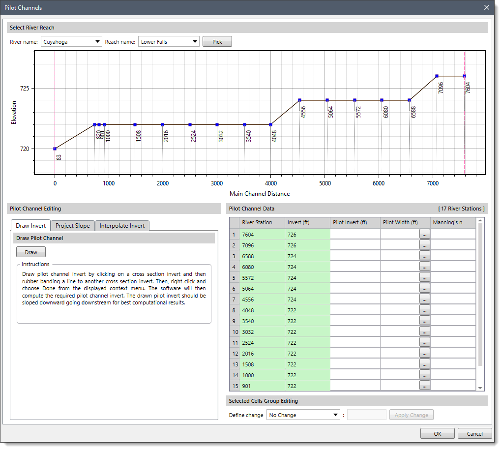
The following sections describe the Pilot Channels command and how to interact with the above dialog box.
The Select River Reach section allows the user to select the river and the reach for defining the pilot channels.
Note that if a river reach has been preselected from the Map View prior to running this command, then the selected river reach will be displayed in the River name and Reach name dropdown combo boxes.
If the model contains a single river and reach, then it will automatically be selected in the River name and Reach name dropdown combo boxes. If the model contains multiple rivers and reaches, then the user can select the desired river and the reach from the River name and Reach name dropdown combo boxes.
Alternatively, the user can click the [Pick] button to select the river and the reach from the Map View. Clicking on the [Pick] button causes the Pilot Channels dialog box to temporarily disappear. The software will then prompt the user to select the river reach from the Map View. After selecting a river reach, the Pilot Channels dialog box will be redisplayed with the river reach shown as selected. The selected river reach is highlighted on the Map View. To abort the selection process, the user can press the [Esc] key or right-click and select Cancel from the displayed context menu.
In addition, a graphical plotting displaying a longitudinal view of the river reach and the pilot channels along the river reach is provided in this section.
This section allows the user to define the parameters for creating a pilot channel. It includes the parameters for defining channel invert over a range of cross sections and the parameters to define a pilot channel cut for the selected cross sections.
The user can select either of the following panels to define pilot channels:
This tabbed panel allows the user to draw the channel invert (channel bottom) along the existing river reach. Click the [Draw] button, and then draw channel invert on the graphical plot available under the Select River Reach section. When finished, right-click and choose Done from the displayed context menu. The software will then automatically compute the required channel invert. Note that the drawn pilot invert should be sloped downward going downstream for the best computational result.
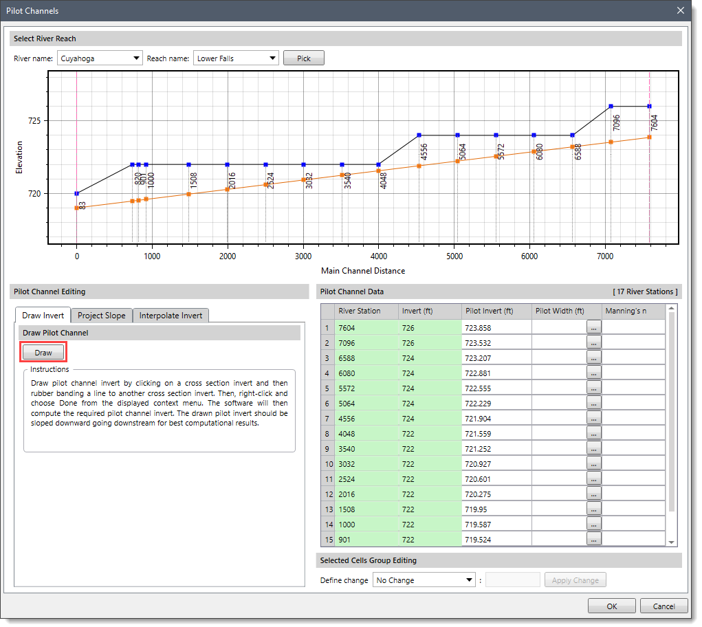
After drawing the pilot channel invert, the user should manually specify the pilot channel width and Manning’s n value in the Pilot Channel Data section to stabilize unsteady flow models.
This tabbed panel allows the user to enter an elevation for the invert of the pilot channel and project it on a slope over the range of cross sections.
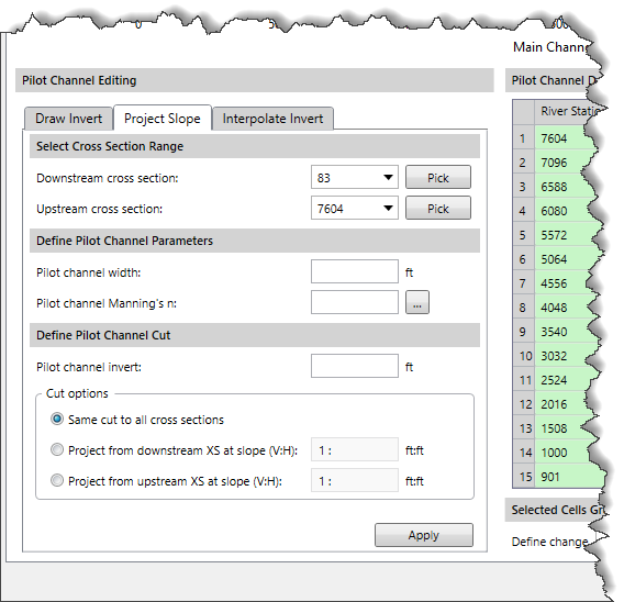
Follow the steps below to define a new channel bottom slope:
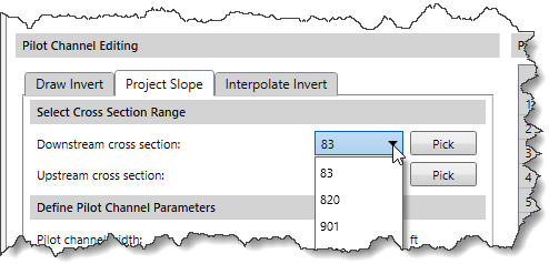
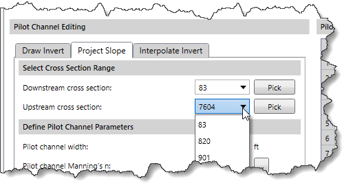 Alternatively, click the [Pick] buttons adjacent to the Downstream cross section and Upstream cross section dropdown combo boxes and select the corresponding cross sections from the Map View. After clicking the [Pick] button, the Pilot Channels dialog box will temporarily disappear. The software will then prompt the user to select the associated cross section from the Map View. After selecting the cross section, the Pilot Channels dialog box will be redisplayed with the cross section shown selected.
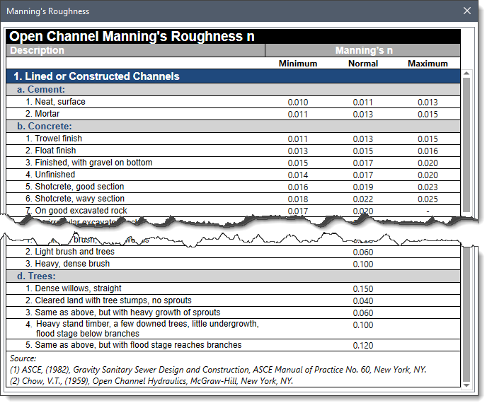
This tabbed panel allows the user to define an invert elevation for the downstream most and the upstream most cross sections, and then automatically interpolate invert elevations for all the cross sections in between the selected range.
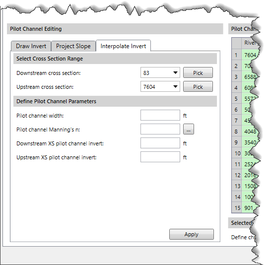
Follow the steps below to interpolate invert elevations:
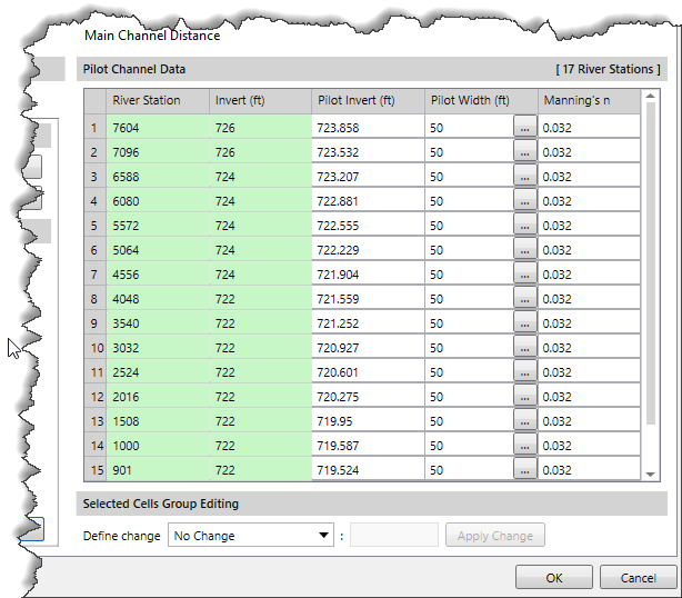
This section provides a table that displays the final pilot channel values for each of the cross sections. The user can modify the table directly and change any value on a cross section-by-cross section basis. Any update in the pilot channel data is automatically reflected in the table.
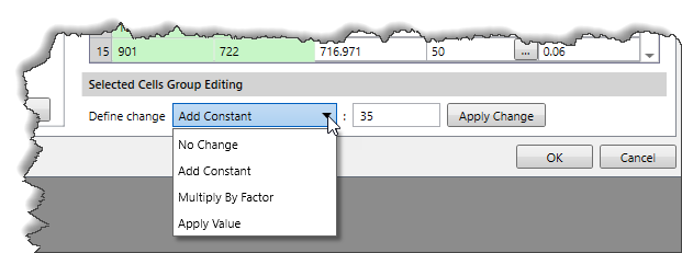
This section allows the user to quickly enter/edit the pilot channel data in the pilot channel summary table (described above).
Follow the steps below to update the pilot channel data:
When all the pilot channel information has been defined in the Pilot Channels dialog box, click the [OK] button, and the software will create a new pilot channel geometry.


CivilGEO G2 Reviews
4.8/5.0 Rating, Over 230 Reviews

GeoHECRAS is recognized as the top Civil Engineering Design Software with an average of 4.8 out of 5.0 rating from over 230 real user reviews on G2.


We use cookies to give you the best online experience. By agreeing you accept the use of cookies in accordance with our cookie policy.
When you visit any web site, it may store or retrieve information on your browser, mostly in the form of cookies. Control your personal Cookie Services here.


