
Welcome to CivilGEO Knowledge Base
Welcome to CivilGEO Knowledge Base
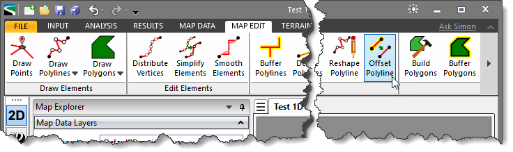
The Offset Polyline command is used to make a copy of a selected polyline using an offset distance on a specified side of the selected polyline. The user can offset a polyline to create a new polyline whose shape is parallel to the original polyline. Furthermore, the tool allows the user to create multiple offsets of a selected polyline where all offset polylines will be separated by a standard distance.
Note that the users can offset any polyline in their model, for example, a river reach or a cross section. While doing so, the new offset polyline will be placed on the Default Drawing Layer.
Follow the steps below to use the Offset Polyline command:
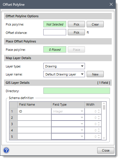
The following sections describe the Offset Polyline command and how to interact with the above dialog box.
This section allows the user to select an existing polyline and define an offset distance to make a copy of this selected polyline.
The following entries are provided in this section:
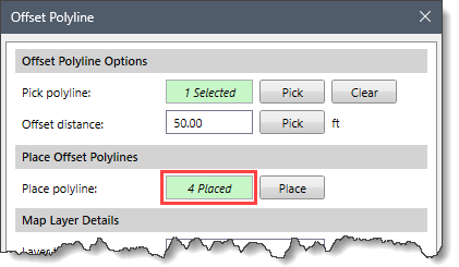
The Place Offset Polylines section allows the user to create the offset polylines on either side of the selected polyline.
Click the [Place] button, and the dialog box will temporarily disappear. The user can then select a point on either side of the selected polyline to place the offset polylines.
![Place] button](https://knowledge.dev.civilgeo.com/wp-content/uploads/sites/25/2024/04/Offset-Polyline-Command-Img-4.png)
Once finished, press the [Enter] key or right-click and select Done from the displayed context menu. The user will be returned to the Offset Polyline dialog box, and the Place polyline read-only field will display the number of polylines placed on the Map View.
Note that after the first offset polyline is placed, the software remembers the originally selected polyline (i.e., selected under the Offset Polyline Options section) and allows the user to place the subsequent offset polylines on either side of the selected polyline.
Consider defining the data for this section before placing offset polyline on the Map View. This section allows the user to create a new general drawing layer or a GIS layer for the offset polylines. By default, the software places the offset polylines in the Default Drawing Layer. When creating a GIS layer, the polylines are saved as a shapefile.
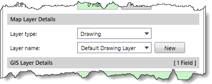
The following entries are provided in the section to define the type and name of the map layer:
This section is enabled when the user selects a GIS layer type. Otherwise, these options are not available.
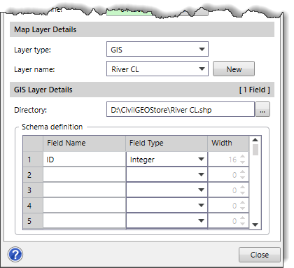
The Directory field defines the path and name of the shapefile to be created. The user can click the […] browse button to select the shapefile directory and file name.
The Schema definition data table allows the user to define the fields to include for the shapefile layer.
This data table requires the following data:


CivilGEO G2 Reviews
4.8/5.0 Rating, Over 230 Reviews

GeoHECRAS is recognized as the top Civil Engineering Design Software with an average of 4.8 out of 5.0 rating from over 230 real user reviews on G2.


We use cookies to give you the best online experience. By agreeing you accept the use of cookies in accordance with our cookie policy.
When you visit any web site, it may store or retrieve information on your browser, mostly in the form of cookies. Control your personal Cookie Services here.


