
Welcome to CivilGEO Knowledge Base
Welcome to CivilGEO Knowledge Base
If a bridge is not oriented perpendicular to the flow lines moving through the bridge, then this type of bridge is known as a skewed bridge. Skewed bridge crossings are typically handled by making adjustments to the bridge dimensions (i.e., bridge deck, piers, etc) to define an equivalent cross section perpendicular to the flow lines.

The skew angle (θ) defines the angle with respect to the flow going through the bridge opening and a line perpendicular to the bridge cross sections. While modeling lower flows, the skew angles below 20 to 30 degrees do not significantly affect the flow patterns through a bridge. The reason for this is that during lower flows, the water/flow lines will be able to turn or pass more easily through the bridge opening than during large flows.
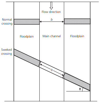
When the user skews the bridge, then he reduces the bridge’s deck/roadway stationing by multiplying the values by cos θ*b. Note that the user should not base the skew angle on the direction of the flow upstream of the bridge. As the water approaches a bridge that is highly skewed, it is common that the flow lines will turn before going through the bridge. A field visit is very important to visualize the flow pattern at the bridge and to help estimate the skew angle.
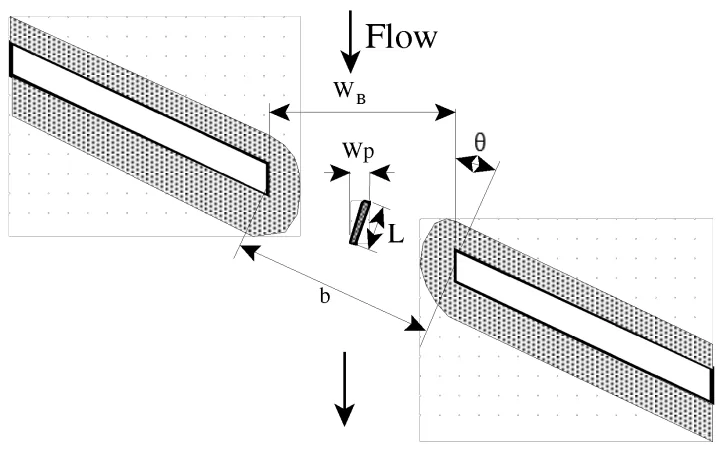
The projected width of the bridge opening, perpendicular to the flow lines, will be computed with the following equation:
WB = cosθ∗b

Note that, as HEC-RAS assumes the piers are continuous, the pier information must also be adjusted to account for the skew of the bridge.
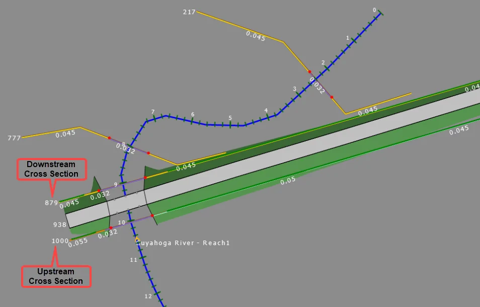
For a skewed bridge, the bounding cross sections (i.e., upstream and downstream) of a bridge should be cut parallel to bridge faces and should be skewed together with the bridge. For example, in the below schematic diagram, 1000 is the upstream cross section and 879 is the downstream cross section.
To define a skew angle to the bridge, open the Bridge & Culvert Data dialog box and then the Deck Roadway panel as shown below.
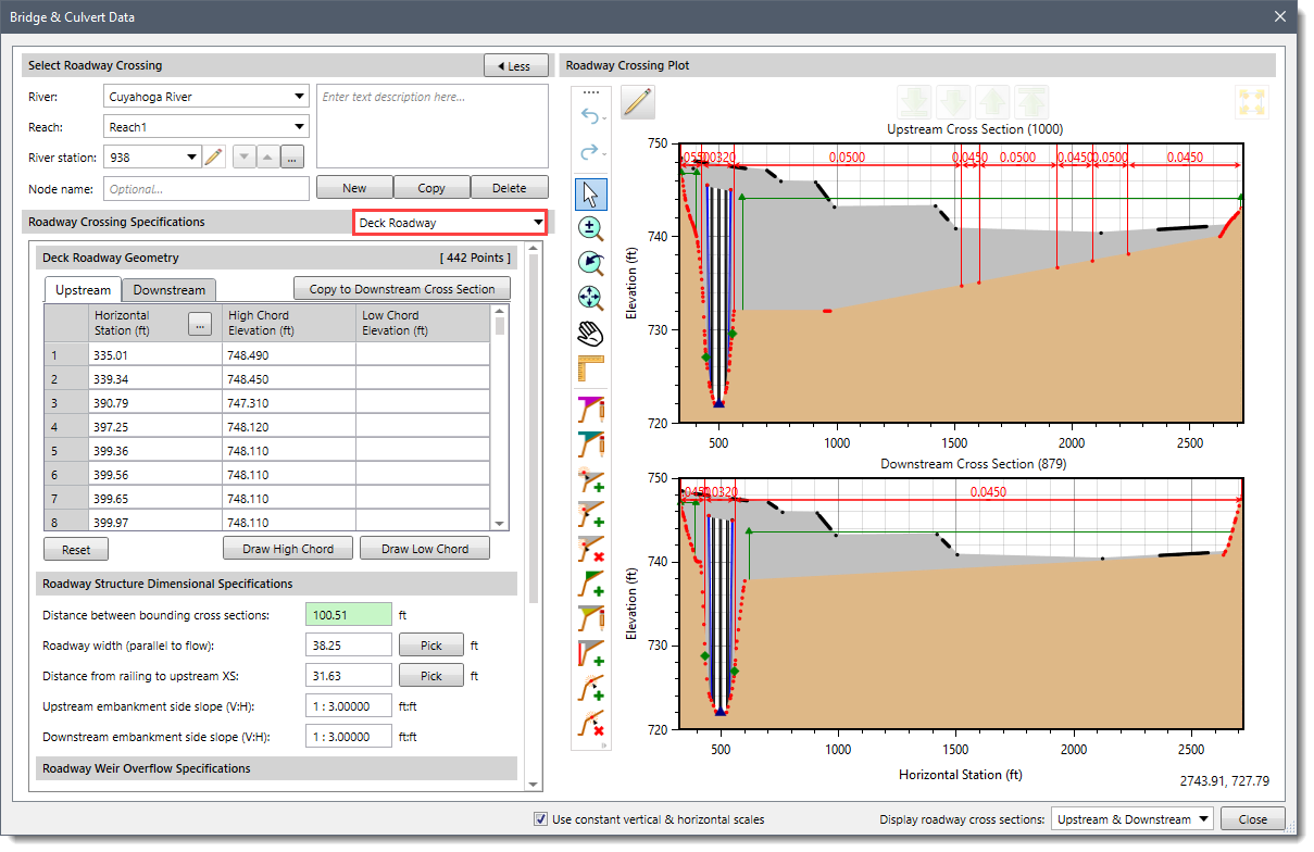
The Roadway Crossing Skew section of the data panel is used to define a skew angle for the roadway crossing and bridge piers.
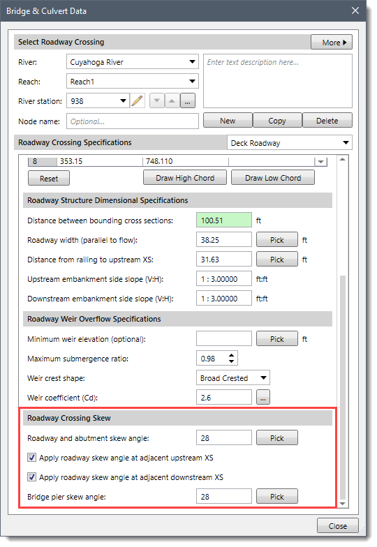
In the Roadway and abutment skew angle entry field, the user can enter the desired skew angle ranging from 0 to 45 degrees. Alternatively, the adjacent [Pick] button can be used to manually measure the skew angle from the Map View.
Once the valid Roadway and abutment skew angle is entered, the software then adjusts the stationing values by multiplying the cosine of the defined angle with each station value contained in the following data:
Refer to this article in our knowledge base to know more about the above points and how to model a HEC-RAS 2D bridge.
The users can then apply the same skew angle to the bounding bridge cross sections by checking the Apply roadway skew angle at adjacent upstream XS and Apply roadway skew angle at adjacent downstream XS checkbox options.
If for some reason the user does not want to skew the bounding cross sections, then he may have to manually alter either the cross section or bridge deck stationing to ensure that the bridge opening correctly aligns with the cross sections.
In a skewed bridge, piers can be either skewed or unskewed. Since HEC-RAS can only handle a continuous pier/bent, a skewed pier will have a very big opening blockage width which depends on the skew angle, bridge deck width, and pier width. For a skewed pier, its skew angle can be different from or the same as the bridge skew angle. The user can provide the skew angle to bridge piers using the Bridge pier skew angle entry field. Alternatively, the adjacent [Pick] button can be used to manually measure the skew angle from the Map View.
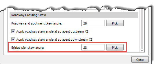
Once the valid Bridge pier skew angle is entered, the software then adjusts each pier width using the following formula:
New Pier Width = (Current Pier Width*Cosine (Pier Skew Angle)) + (Roadway Width*Sine (Pier Skew Angle))
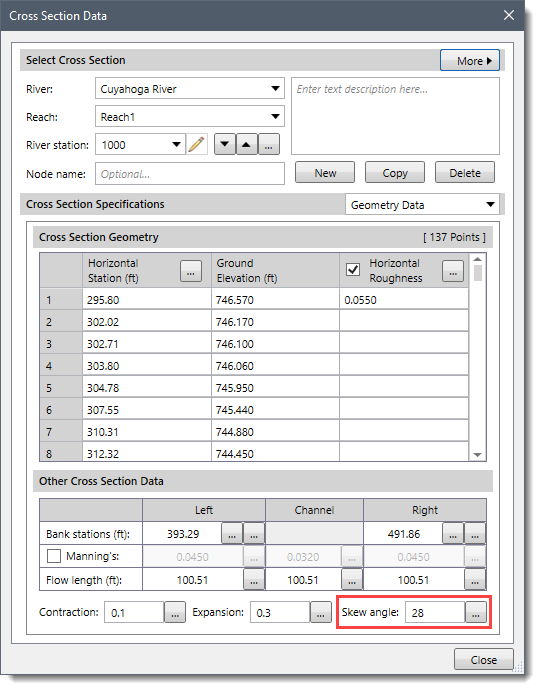
Note that entering the Roadway and abutment skew angle field value keeping the Apply roadway skew angle at adjacent upstream XS and Apply roadway skew angle at adjacent downstream XS checkboxes checked, automatically fills the corresponding Skew angle in the Cross Section Data dialog box as shown below.
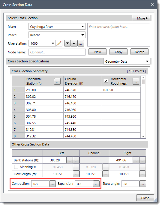
After defining the roadway and abutment skew angle, the ineffective flow areas should be established at upstream and downstream cross sections using Contraction and Expansion coefficients for low flows or pressure flows to pass through the bridge opening. Refer to this article in our knowledge base to learn more about HEC-RAS ineffective flow areas.
For typical bridge cross sections, the Contraction and Expansion coefficients should be set to 0.3 and 0.5 respectively. Refer to this article in our knowledge base to learn more about contraction and expansion losses in HEC-RAS.
When a weir flow passes the bridge opening (overtopping bridge deck), the defined ineffective flow areas should be turned off. For this reason, the elevation of ineffective flow areas at the upstream cross section should be set up initially as the low point of the top of the road. Also, for the downstream cross section, its ineffective flow area elevation should be initially set up somewhere in between the low point of the top of the road and the low chord.
After defining the bridge skew and other associated parameters, the analysis should be computed with the incorporated changes in the model. The modeled skewed bridge then will have all the changes, and the computational results can be viewed from the Cross Section plot. Refer to this article in our knowledge base to learn more about HEC‑RAS cross section output plots.


CivilGEO G2 Reviews
4.8/5.0 Rating, Over 230 Reviews

GeoHECRAS is recognized as the top Civil Engineering Design Software with an average of 4.8 out of 5.0 rating from over 230 real user reviews on G2.


We use cookies to give you the best online experience. By agreeing you accept the use of cookies in accordance with our cookie policy.
When you visit any web site, it may store or retrieve information on your browser, mostly in the form of cookies. Control your personal Cookie Services here.


