
Welcome to CivilGEO Knowledge Base
Welcome to CivilGEO Knowledge Base
CivilGEO’s software uses a projected coordinate reference system (CRS) to create an engineering model. It lets the user bring in GIS, CAD, TIN, and other data files which are in a different coordinate system, and automatically map them according to the project CRS.
However, sometimes when a projection file layer with data that has been converted from 3D spheroid (Earth) survey data into a projection map is added to a project, it may not necessarily map in the same coordinate space as the rest of the data. This issue occurs because all map projections have distortions.
The transformation scale factor is a way to reduce the distortion over a particular area, so that a dimension on the flat projection map is as close as it can get to the spherical Earth measurement. AutoCAD Civil 3D provides support for the transformation scale factor in its Drawing Settings dialog box.
In our software, the transformation scale factor is supported throughout the software, including CAD layers, TIN layers, and other layers. This is accomplished by using the layer properties dialog boxes to automatically apply transformation scale factor on any particular layer and accurately map it to the project coordinate reference system (CRS).
In addition, a layer’s position may be registered manually by providing two coordinate points (i.e., the source and the target location).
Follow the steps below to apply a layer transformation and its registration on the desired layer:
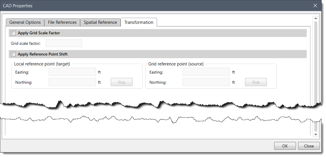
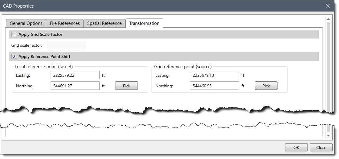
The following sections describe how to use the Transformation tab and how to interact with the above dialog box.
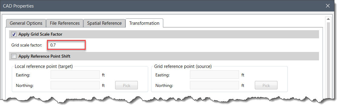
This option permits the application of grid scaling factor on a layer to match the layer’s dimensions to the project CRS. The Grid scale factor is the measure of distortion at a point on a projected map. It is used to calculate the actual ellipsoidal distances as per the true shape of the Earth, which is not a perfect sphere. To apply grid scale factor on a layer, follow these steps:
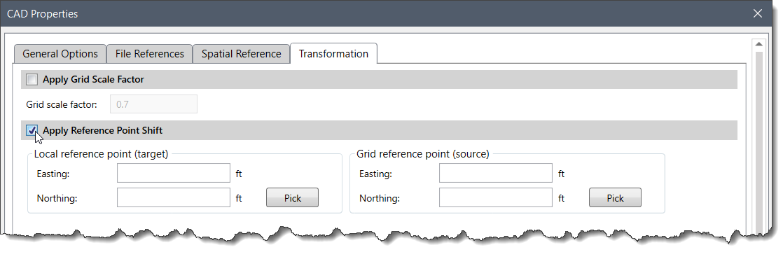
This option allows quick registration of a layer that is not mapped correctly according to the project CRS. The user can specify the coordinate points for the target and the source locations. To apply reference point shift on a layer, follow these steps:
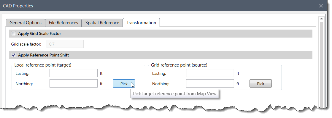
Alternatively, the user can interactively pick the target and source locations from the Map View to automatically register the layer. To use this alternate method, follow these steps:


CivilGEO G2 Reviews
4.8/5.0 Rating, Over 230 Reviews

GeoHECRAS is recognized as the top Civil Engineering Design Software with an average of 4.8 out of 5.0 rating from over 230 real user reviews on G2.


We use cookies to give you the best online experience. By agreeing you accept the use of cookies in accordance with our cookie policy.
When you visit any web site, it may store or retrieve information on your browser, mostly in the form of cookies. Control your personal Cookie Services here.


