
Welcome to CivilGEO Knowledge Base
Welcome to CivilGEO Knowledge Base
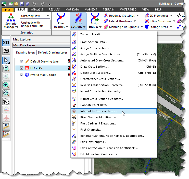
The Interpolate Cross Sections command can be used to automatically add interpolated cross sections to a river reach. The interpolated cross sections can be added for an entire river reach or just part of a reach.
While it is always better to define “real” cross sections by extracting the cross sections from an underlying terrain surface, there are times when this is not feasible. For example, the existing cross sections might have been created by compositing the overbank geometry with the channel geometry using different data sources. The overbank geometry might have been extracted from a terrain surface, whereas the channel geometry may have been constructed from field survey data. In these situations, the Interpolate Cross Sections command can be used to fill-in cross sections between the existing cross sections. If desired, after the interpolated cross sections have been constructed, the user can then re-extract only the overbank geometry from the terrain surface using the Extract Cross Section Geometry command to create more accurate interpolated cross sections. Refer to this article in our knowledge base to learn more about the Extract Cross Section Geometry command.
Interpolated cross sections are useful when there is too large of a change in the velocity head between existing cross sections and the software cannot accurately calculate the energy gradient. An adequate depiction of the energy gradient change is important for accurately modeling friction losses as well as contraction and expansion losses. HEC-RAS will report the following warning messages for these situations as well as other situations where additional cross sections may be required:
When adding interpolated cross sections, the software will automatically add and space the cross sections along the river reach as per the user-defined specifications, positioning the cross sections perpendicular to the channel centerline.
Follow the steps below to add interpolated cross sections:
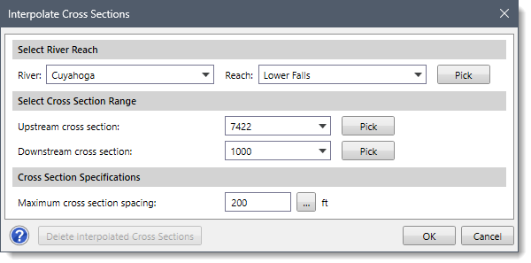
The following sections describe how to use the Interpolate Cross Sections command and interact with the above dialog box.
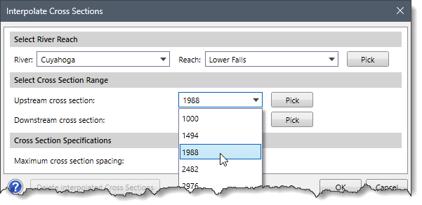
The Select River Reach section describes how to select the river reach for performing automatic cross section interpolation. Follow the steps below:
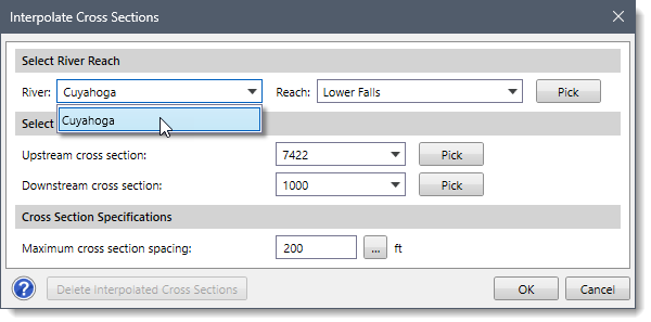
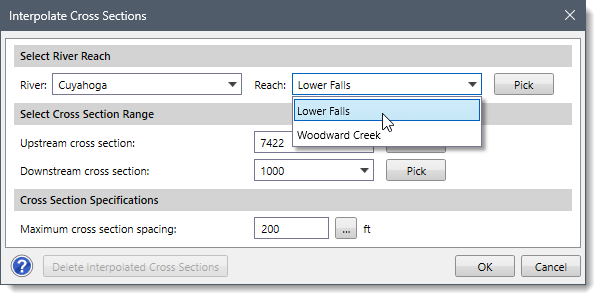
Alternatively, click the [Pick] button to select the river reach from the Map View. The Interpolate Cross Sections dialog box will temporarily disappear. The software will then prompt the user to select the river reach from the Map View. After selecting a river reach, the Interpolate Cross Sections dialog box will be redisplayed and the selected river reach will be shown in the River and Reach dropdown combo boxes.
The Select Cross Section Range section is used to define the cross section range along the selected river reach, in which the cross section interpolation will be applied. Follow the steps below:
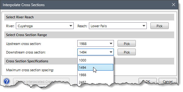
Alternatively, click the [Pick] buttons adjacent to the Upstream cross section and Downstream cross section dropdown combo boxes and select the corresponding cross sections from the Map View. The Interpolate Cross Sections dialog box will temporarily disappear. The software will then prompt the user to select the associated cross section from the Map View. After selecting a cross section, the Interpolate Cross Sections dialog box will be redisplayed and the selected cross section will be shown in the Upstream cross section and Downstream cross section dropdown combo boxes.
This section is used to define the maximum allowable distance between cross sections. If the channel distance between any two existing cross sections is greater than the maximum allowable distance defined by the user, then the software will interpolate cross sections between these two cross sections. The software will interpolate as many cross sections as necessary to get the distance between the cross sections below the specified maximum allowable distance.
Enter the distance for the Maximum cross section spacing entry field. Alternatively, click the […] button to measure the cross section spacing from the Map View. The Interpolate Cross Sections dialog box will temporarily disappear. The software will then prompt the user to measure the maximum cross section spacing distance from the Map View. When finished, press the [Enter] key or right-click and choose Done from the displayed context menu. The Interpolate Cross Sections dialog box will be redisplayed and the measured distance will be shown in the Maximum cross section spacing entry field.
The [Delete Interpolated Cross Sections] button can be used to delete previously created interpolated cross sections for the selected river reach. Note that this button is disabled if there are no interpolated cross sections defined for the selected river reach. Alternatively, the Delete Cross Sections command can be used to interactively delete the selected cross sections. Refer to this article in our knowledge base to learn more about the Delete Cross Sections command.
![[Delete Interpolated Cross Sections] button](/wp-content/uploads/sites/25/2023/10/Interpolate-Cross-Sections-Command-Img-7.png)
After the cross section interpolation options have been defined, click the [OK] button and the software will interpolate the cross sections.![[OK] button](/wp-content/uploads/sites/25/2023/10/Interpolate-Cross-Sections-Command-Img-8.png)


CivilGEO G2 Reviews
4.8/5.0 Rating, Over 230 Reviews

GeoHECRAS is recognized as the top Civil Engineering Design Software with an average of 4.8 out of 5.0 rating from over 230 real user reviews on G2.


We use cookies to give you the best online experience. By agreeing you accept the use of cookies in accordance with our cookie policy.
When you visit any web site, it may store or retrieve information on your browser, mostly in the form of cookies. Control your personal Cookie Services here.


