
Welcome to CivilGEO Knowledge Base
Welcome to CivilGEO Knowledge Base
The program is capable of modeling both radial gates (often called tainter gates), vertical lift gates (sluice gates), and overflow gates. The equations used to model the gate openings can handle both submerged and unsubmerged conditions at the inlet and the outlet of the gates. When the gates are opened to an elevation greater than the upstream water surface elevation, the program automatically switches to modeling the flow through the gates as weir flow. When the upstream water surface is greater than or equal to 1.25 times the height of the gate opening (with respect to the gates spillway crest), the gate flow equations are applied. When the upstream water surface is between 1.0 and 1.25 times the gate opening, the flow is in a zone of transition between weir flow and gate flow. The program computes the upstream head with both equations and then calculates a linear weighted average of the two values (this is an iterative process to obtain the final headwater elevation for a flow in the transition range). When the upstream water surface is equal to or less than 1.0 times the gate opening, then the flow through the gate opening is calculated as weir flow.
An example radial gate with an ogee spillway crest is shown in Figure 1.
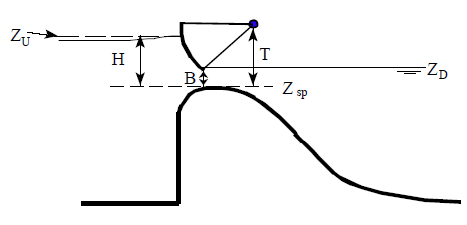
Figure 1. Example Radial Gate with an Ogee Spillway Crest
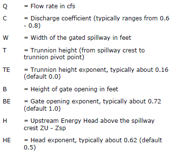
The flow through the gate is considered to be “Free Flow” when the downstream tailwater elevation (ZD) is not high enough to cause an increase in the upstream headwater elevation for a given flow rate. The equation used for a Radial gate under free flow conditions is as follows:
| |
(1) |
Where:
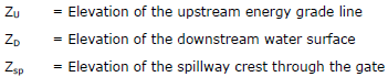
When the downstream tailwater increases to the point at which the gate is no longer flowing freely (downstream submergence is causing a greater upstream headwater for a given flow), the program switches to the following form of the equation:
| |
(2) |
![]()
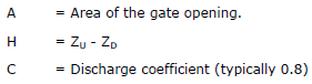
Submergence begins to occur when the tailwater depth divided by the headwater energy depth above the spillway, is greater than 0.67. Equation 2 is used to transition between free flow and fully submerged flow. This transition is set up so the program will gradually change to the fully submerged Orifice equation when the gates reach a submergence of 0.80. The fully submerged Orifice equation is shown below:
| |
(3) |
Where:
An example sluice gate with a broad crest is shown in Figure 2.
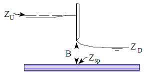
Figure 2. Example Sluice Gate with Broad Crested Spillway
The equation for a free flowing sluice gate is as follows:
| |
(4) |
Where:
![]()
![]()
When the downstream tailwater increases to the point at which the gate is no longer flowing freely (downstream submergence is causing a greater upstream headwater for a given flow), the program switches to the following form of the equation:
| |
(5) |
Where:
![]()
Submergence begins to occur when the tailwater depth above the spillway divided by the headwater energy above the spillway, is greater than 0.67. Equation 5 is used to transition between free flow and fully submerged flow. This transition is set up so the program will gradually change to the fully submerged Orifice equation (Equation 3) when the gates reach a submergence of 0.80.
Overflow gates represent a gate in which the bottom of the gate moves up and down. Overflow gates can be completely open to the air at the top, or the top can be closed off. An example of an overflow gate is shown below in Figure 3.
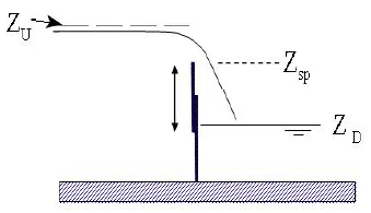
Figure 3. Example Overflow Gate
Overflow gates are generally modeled with the standard weir equation:
| |
(6) |
Where:
C = Weir flow coefficient, typical values will range from 2.6 to 4.0 depending upon the shape of the spillway crest (i.e., broad crested, ogee shaped, or sharp crested). Most overflow spillways tend to be sharp crested, so a value of 3.2 is typical.
L = Length of the spillway crest.
H = Upstream energy head above the spillway crest.
For overflow gates in which the Sharp Crested spillway crest shape is selected, the user has the option of using the standard weir equation, The Rehbock equation (Henderson, 1966), or the Kindsvater and Carter equation (1957).
When the upstream water surface is equal to or less than the top of the gate opening, the program calculates the flow through the gates as weir flow. An example of low flow through a gated structure is shown in Figure 4.
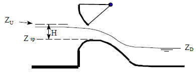
Figure 4. Example Radial Gate Under Low Flow Conditions
The standard weir equation used for this calculation is shown below:
| |
(7) |
Where:
C = Weir flow coefficient, typical values will range from 2.6 to 4.1 depending upon the shape of the spillway crest (i.e., broad crested, ogee shaped, or sharp crested).
L = Length of the spillway crest.
H = Upstream energy head above the spillway crest.
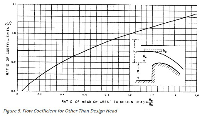
The user can specify either a broad crested, ogee, or sharp crested weir shape for the spillway crest of the gate. If the crest of the spillway is ogee shaped, the weir coefficient will be automatically adjusted when the upstream energy head is higher or lower than a user specified design head. The adjustment is based on the curve shown in Figure 5 (Bureau of Reclamation, 1977). The curve provides ratios for the discharge coefficient, based on the ratio of the actual head to the design head of the spillway. In Figure 5, He is the upstream energy head; Ho is the design head; Co is the coefficient of discharge at the design head; and C is the coefficient of discharge for an energy head other than the design head.
The program automatically accounts for submergence on the weir when the tailwater is high enough to slow down the flow. Submergence is defined as the depth of water above the weir on the downstream side divided by the headwater energy depth of water above the weir on the upstream side. As the degree of submergence increases, the program reduces the weir flow coefficient. Submergence corrections are based on the shape of the spillway crest (broad crested, ogee shaped weir, or sharp crested). If the spillway is a broad crested shape, then the same submergence curve that is used for flow over a roadway at a bridge is used, as shown in Figure 6. If the spillway crest is ogee shaped, a submergence curve from the USACE EM 1110-2-1603 (plate 3-5, A-A) is used. If the spillway is sharp crested, then the Villemonte equation (Villemonte, 1947) is used to compute the flow reduction coefficient.
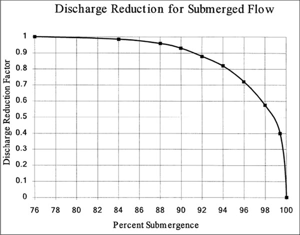
Figure 6. Factor for Reducing Weir Flow for Submergence


CivilGEO G2 Reviews
4.8/5.0 Rating, Over 230 Reviews

GeoHECRAS is recognized as the top Civil Engineering Design Software with an average of 4.8 out of 5.0 rating from over 230 real user reviews on G2.


We use cookies to give you the best online experience. By agreeing you accept the use of cookies in accordance with our cookie policy.
When you visit any web site, it may store or retrieve information on your browser, mostly in the form of cookies. Control your personal Cookie Services here.


