
Welcome to CivilGEO Knowledge Base
Welcome to CivilGEO Knowledge Base
In order to perform unsteady flow analysis, unsteady flow data are required. Unsteady flow data consist of boundary conditions as well as initial conditions. To learn how to establish boundary conditions for unsteady flow analysis, refer to this article in our knowledge base.
In addition to the boundary conditions, the user must establish the initial conditions of the system at the beginning of the unsteady flow simulation. Initial conditions must be set up appropriately not to make the model crash or become unstable at the beginning of the modeling exercise. Initial conditions consist of flow and stage information at each of the cross sections and elevations for any storage area or 2D flow area defined in the system. Initial conditions can be established in two different ways. The most common way is to enter flow data for each reach and then have the software compute water surface elevations by performing a steady flow backwater analysis. The second method can only be used if a previous run was made. This method allows the user to write a file of flow and stage from a previous run (Restart File), which can then be used as the initial conditions for a subsequent run.
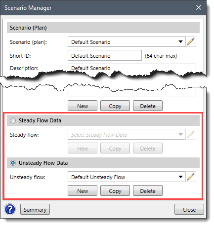
Note that the user can switch between the steady and unsteady flow data of the model from the Scenario Manager dialog box as shown below. To learn more about the Scenario Manager command, refer to this article in our knowledge base.
To establish initial conditions for unsteady flow analysis, follow these steps:
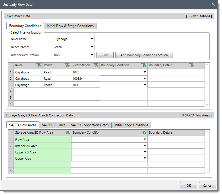
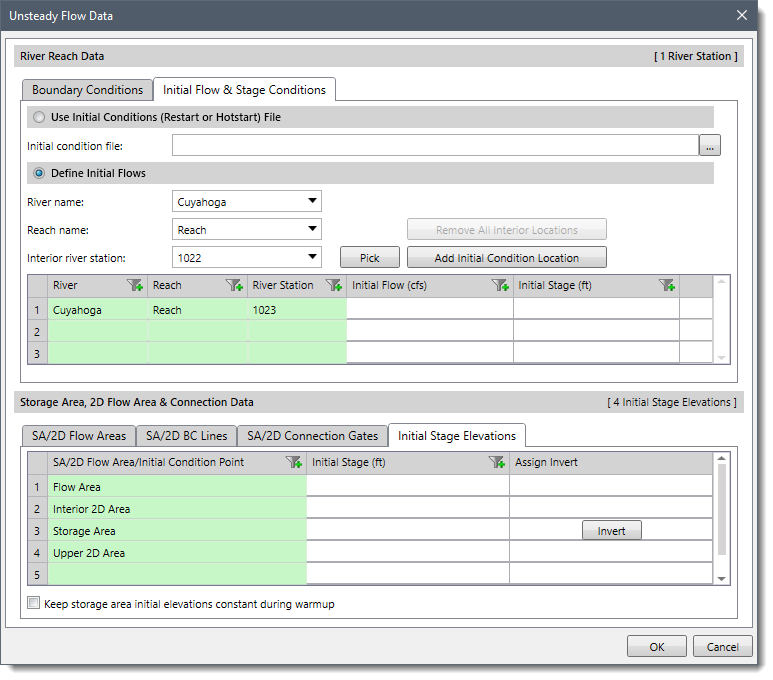
The user can establish the initial conditions of the system using either the Use Initial Conditions (Restart or Hotstart) File option or the Define Initial Flows option. The Initial Stage Elevations tab can be used to define the starting water surface elevation in any storage area and 2D flow area defined in the system.
The below sections describe how to establish the initial conditions and interact with the above panel.
This option allows the user to read in stages and flows from a Restart File. If a previous run has been made, and the option to write out a Restart File was used, then a Restart File can be used to establish the initial conditions for the subsequent run. Refer to this article in our knowledge base to learn how to create a Restart File. The user can click the […] button to browse to the location of the desired Restart File and select it.
Generally, this option is used when running a long simulation time that must be divided into shorter periods. The output from the first period is used as the initial conditions for the next period, and so on. In addition, this option may be used when the software is having stability problems at the beginning of a run. Occasionally the model may go unstable at the beginning of a simulation due to bad initial conditions. When this happens, one way to fix the problem is to run the model with all the inflow hydrographs set to a constant flow and set the downstream boundaries to a high tailwater condition. Then run the model and decrease the tailwater down to a normal stage over time (use a stage hydrograph downstream boundary to do this). Once the tailwater is decreased to a reasonable value, those conditions can be written out to a file and used as the starting conditions for the unsteady flow run.
This option allows the user to enter flow data for each reach and have the program perform a steady flow backwater analysis to compute the corresponding stages at each cross section. This is the most common method for establishing initial conditions.
The user can select the river and corresponding reach for which the flow data are to be entered from the River name and Reach name dropdown combo boxes, respectively. All the river stations belonging to the selected reach will be listed under the Interior river station dropdown combo box.
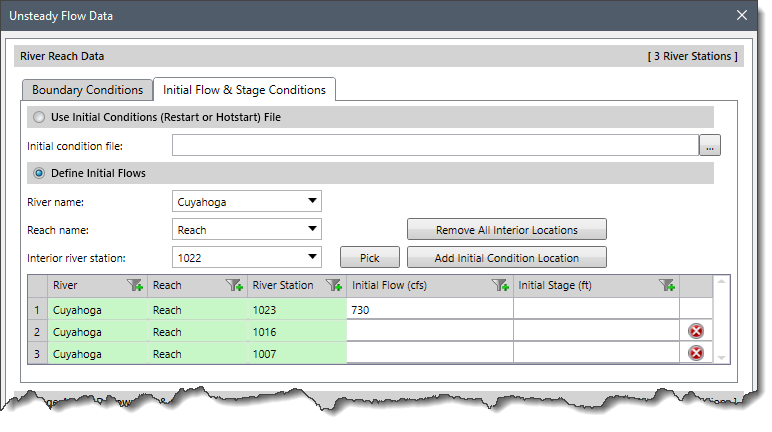
The user can enter flow data for any number of river stations under the Initial Flow column, but at a minimum, the user must enter a flow at the upper end of each reach. The software automatically adds the river station at the upper end of the reach into the table. To add additional river station locations, the user can select the desired river station from the Interior river station dropdown combo box and click the [Add Initial Condition Location] button to include it in the table.
If it is required to remove all the interior river station locations from the table at once, click the [Remove All Interior Locations] button.
If the river system is dendritic (no loops anywhere in the system), the user can leave all the flow data fields blank. The software will get flow data from the first value of all the boundary condition hydrographs (Upstream and lateral inflows). Flows are set from upstream to downstream by adding flows together at junctions as appropriate.
Initial conditions for 2D flow areas and storage areas can be set in several ways. They can start completely dry or be set to a constant water surface elevation or set by using a Restart File from a previous run (as discussed in first section).
The Initial Stage Elevations tab lists all the storage areas and 2D flow areas contained within the system. The Initial Stage column of this tab can be left blank to simulate the area “starting dry.” Alternatively, the user can start with a constant water surface elevation by entering an elevation value for each storage area and 2D flow are in the Initial Stage column. Additionally, the user can click the [Invert] button to assign an invert elevation for the storage area.
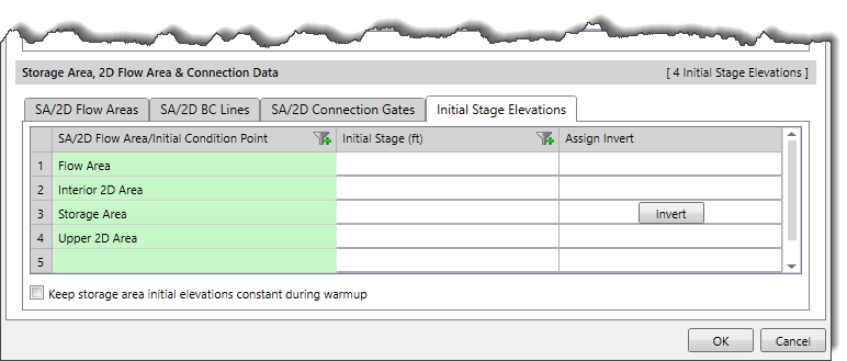
Note that the area connected directly to the upstream or downstream end of a 1D reach cannot start dry.
The GeoHECRAS default setting does not perform a warm up period. However, if a model becomes unstable at the beginning of a run, users can direct the software to run several iterations before the start of the simulation in which all inflows are held constant (warm up). The warm up run does not advance in time and the actual simulation only starts after the warm up run ends. By default, the water surface level in storage areas is allowed to change during the warm up period based on the net flow. If the Keep storage area initial elevations constant during warm up checkbox is checked, then the water surface levels in the storage areas will be held at the user entered value during the warm up period (e.g., a dry storage area will still be dry at the end of the warm up even if it had incoming flow). If a warm up period is not used, then this option will have no effect.
Refer to this article in our knowledge base to learn how to perform a warm up run.
The warm up option is for the entire HEC-RAS model element, including 1D and 2D. However, 2D flow areas have an additional option called ramp up option. This option is used to ramp up the water surface from dry to wet conditions within a 2D area. If there is water flowing into or out of a 2D area at the beginning of the simulation, this option must be turned on to establish initial conditions. Normally 2D ramp up happens before the start of the overall model warm up. The ramp up option allows users to specify a time (in hours) to run the computations for the 2D flow area, by slowly transitioning the flow boundaries from zero to their initial value, and the stage boundaries from a dry elevation up to their initial wet elevation. Users specify the total Initial Conditions Time (2 hours, for example) and a fraction of this time (Initial Condition Ramp-up Fraction) for ramping up the boundary conditions. A value of 0.1 means that 10% of the Initial Conditions time will be used to ramp up the boundary conditions to their initial values, the remaining time will be used to hold the initial boundary conditions constant but allow the flow to propagate through the 2D flow area, thus giving it enough time to stabilize to a good initial condition throughout the entire 2D flow area.
Refer to this article in our knowledge base to learn more about how to turn on the ramp up option.


CivilGEO G2 Reviews
4.8/5.0 Rating, Over 230 Reviews

GeoHECRAS is recognized as the top Civil Engineering Design Software with an average of 4.8 out of 5.0 rating from over 230 real user reviews on G2.


We use cookies to give you the best online experience. By agreeing you accept the use of cookies in accordance with our cookie policy.
When you visit any web site, it may store or retrieve information on your browser, mostly in the form of cookies. Control your personal Cookie Services here.


