
Welcome to CivilGEO Knowledge Base
Welcome to CivilGEO Knowledge Base
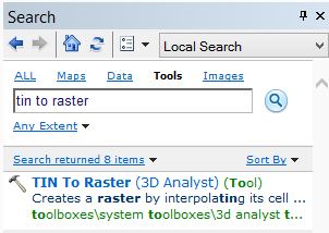
This article and video demonstrates how to convert an ESRI TIN file to an elevation raster using ArcGIS and the 3D Analyst extension.
A Triangulated Irregular Network (TIN) is a vector representation of a ground surface. An elevation raster (grid) dataset represents the height of the ground using pixel values.
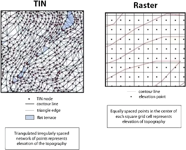
While both formats store elevation data, TINs are less widely supported in GIS and CAD packages. They are also more computationally intensive to render, and large datasets can take a long time to draw on screen. In addition, ESRI TIN and Terrain Datasets are in proprietary format and are only supported by ESRI software products making it very difficult to share with other software applications.
Elevation rasters on the other hand are faster to render, and are supported by a wider variety of software applications.
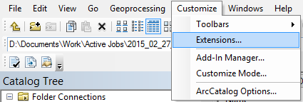
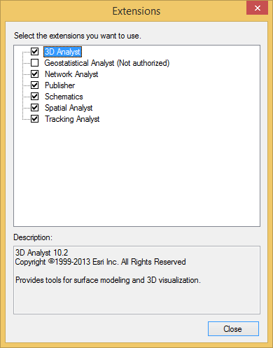
To manipulate TIN elevation data, the 3D Analyst extension must be enabled.
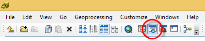
To enable the 3D Analyst extension, follow these steps:
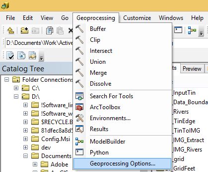
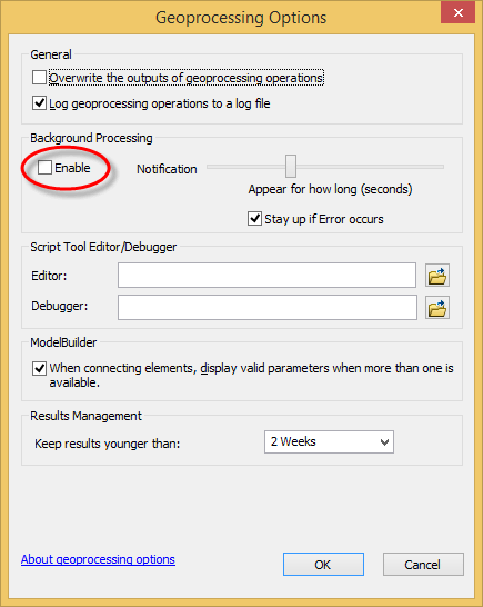
ArcGIS has two available modes for processing data:
Both modes will work for this tutorial; however they will affect what you see on screen. This tutorial will use foreground geoprocessing as it provides more diagnostic information in case of errors.
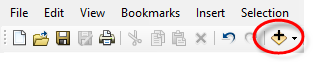
To enable foreground geoprocessing, follow these steps:
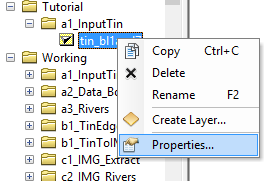
Before converting the TIN to an elevation raster, it is important to check the integrity of the TIN data to determine if any modifications need to be made.
To validate the TIN data, follow these steps:
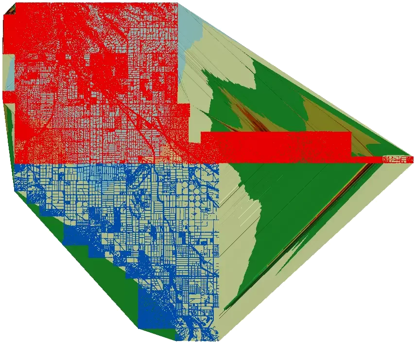
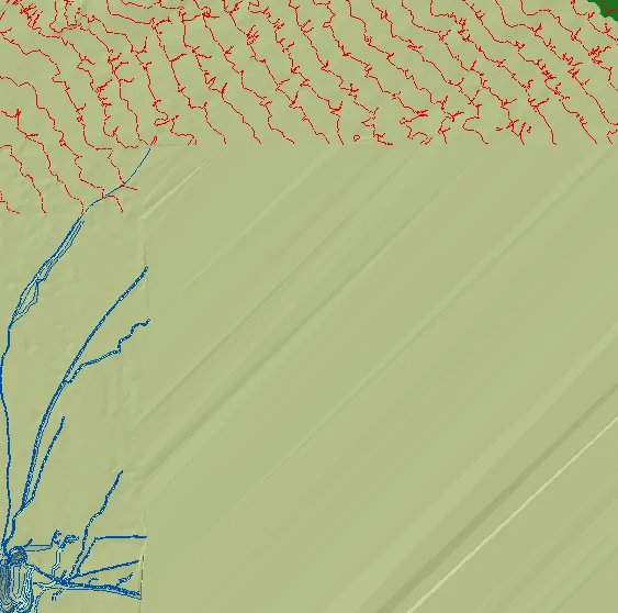
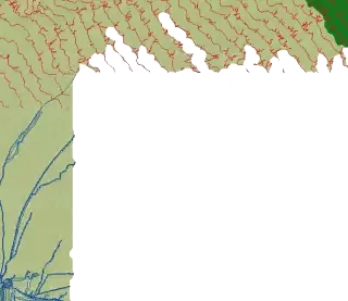
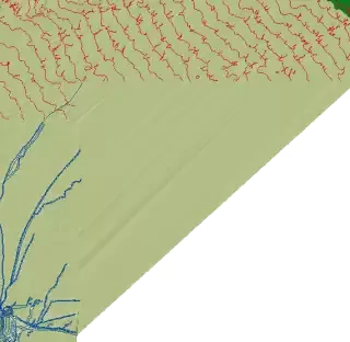
In the above illustration the red and blue lines actually represent two different elevation point data sets that were used to construct the TIN. This elevation point data are used as the vertices of the TIN triangles. In the above illustration the TIN triangle edges are not visible. However, the triangle edges represent interpolated elevations and the shaded areas between the the triangle edges represent linear elevation (flat planar) surfaces. ArcGIS uses the linear elevation surfaces to compute elevations for locations within the areas between the triangle edges.
In this example the shaded areas extend beyond the extents of the elevation point data (i.e., TIN vertices). By default, ArcGIS constructs a convex hull boundary of the elevation data and constructs a TIN within it. However, as can be seen below, the TIN triangles (shaded areas) extend beyond the elevation point data. This will be corrected by delineating the TIN elevation data area.
To stop ArcGIS constructing TIN triangles beyond the extents of the elevation point data, we will define elevation area limits where there is valid elevation data. It is important to perform this step before converting the TIN to an elevation raster or otherwise the elevation raster will contain the same invalid elevation areas as the TIN.
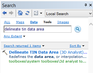
To delineate the TIN elevation data area, follow these steps:
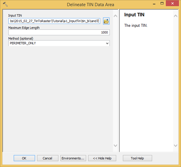
The Delineate TIN Data Area tool works by removing TIN triangles that have a triangle edge longer than the specified maximum edge length. The concept is that most valid elevation areas are made up of TIN triangles with short edge lengths, and invalid elevation areas have TIN triangles with longer edge lengths. Generally, invalid elevation areas occur on the perimeter of the TIN dataset due to the creation of the convex hull area. However, if there are large areas inside the TIN that do not contain elevation data (e.g., lakes and rivers), change the Method to All.
There is no rule on what value to enter for the Maximum Edge Length field. Smaller values will remove more triangles, but can also remove valid elevation areas from the TIN dataset. Larger values eliminate fewer triangles, but can leave invalid elevation areas in the TIN dataset. Trial and error is used to determine an appropriate value to use. The Delineate TIN Data Area tool can be run multiple times on the same dataset; each iteration overwrites the previous results. It is not necessary to run the Delineate TIN Data Area tool on a fresh copy of the TIN each time.
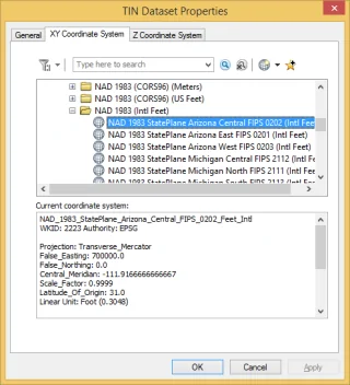
The TIN’s XY coordinate system determines the unit of measurement for the Maximum Edge Length field. For example, if the TIN is in NAD83 State Plane coordinates, the units will be in feet. If the TIN is in WGS84 UTM coordinates, the units will be in meters.
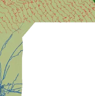
TIN elevation data set after running Delineate TIN Data Area tool with different Maximum Edge Length values. From top to bottom, 100 ft, 1000 ft, and 5000 ft.
Once you are satisfied with the delineated TIN elevation data area, it is ready to be converted to an elevation raster.
To convert the TIN to an elevation raster, follow these steps:
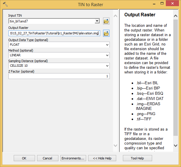
When entering a file name for the output raster, the file extension determines what format the raster will be saved as. For example, entering “elevation.img” will save the elevation raster as an ERDAS Imagine elevation file. Leaving the extension blank will save the elevation raster as an ESRI binary grid elevation raster. In the above dialog box, the raster is saved as an .img file as ERDAS Imagine elevation raster files do not have file name or size limitations as do ESRI elevation grid files and GeoTIFF files.
Floating point (float) elevation rasters are the default raster type. Float elevation raster files store elevation information with a higher precision than integer elevation rasters as they store the elevation data with decimal information (e.g., 10.35 feet versus 10 feet). The downside of float elevation raster files is the extra precision makes the files larger than integer elevation raster files.
The Z Factor field is used to convert between different elevation units. For example, if the TIN’s elevation units are in meters and you need the elevation raster units in feet, you would enter a Z Factor of 3.28084 (i.e., 3.28084 feet = 1 meter). Conversely, if the TIN elevation units are in meters and you need the elevation raster units in meters, you would enter a Z Factor of 0.3048 (i.e., 0.3048 meter = 1 foot).
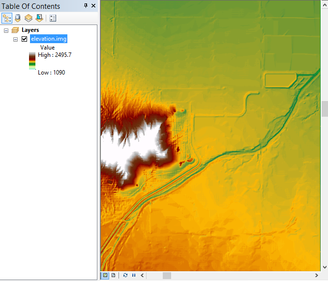
Once the TIN to Raster tool has completed, open the output raster in ArcMap to check for any errors. The below image shows the computed raster elevation results.
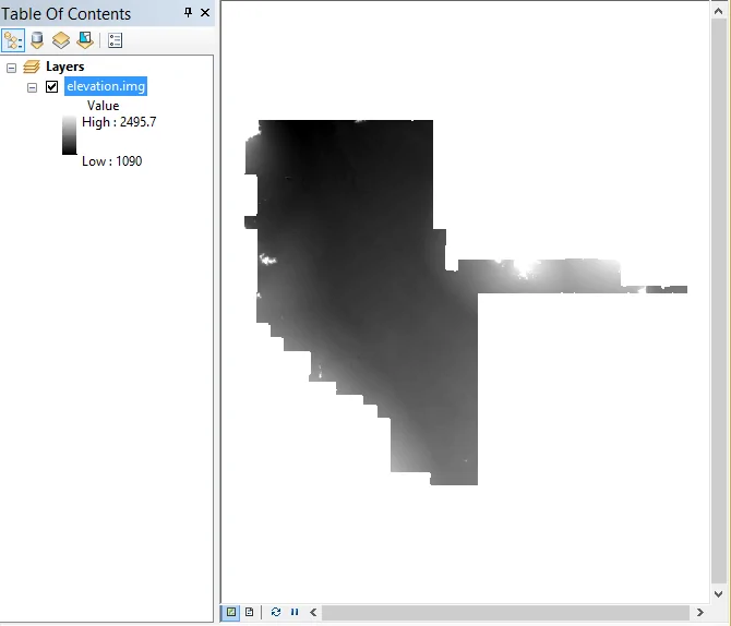
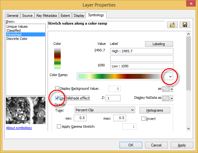
If you want to view a colorized version of the image, right click in the Table Of Contents on the image entry and select Properties from the displayed context menu. The Layer Properties dialog box will be displayed.
In the displayed dialog box, select the Symbology tab. Then, from the Color Ramp dropdown combo box, select an appropriate color ramp. To add a 3D effect to the displayed elevation raster, check the Use hillshade effect option. These settings do not alter the raster elevation data, only how it is displayed in ArcMap.


CivilGEO G2 Reviews
4.8/5.0 Rating, Over 230 Reviews

GeoHECRAS is recognized as the top Civil Engineering Design Software with an average of 4.8 out of 5.0 rating from over 230 real user reviews on G2.


We use cookies to give you the best online experience. By agreeing you accept the use of cookies in accordance with our cookie policy.
When you visit any web site, it may store or retrieve information on your browser, mostly in the form of cookies. Control your personal Cookie Services here.


