A shapefile is a nontopological file format for storing the geometric location and attribute information of geographic features. Geographic features in a shapefile can be represented by points, lines, or polygons (areas).
In GeoHECHMS, the Import HEC-HMS Shapefile Geometry command allows the user to import the GIS geometry data shapefiles that represent the major components of a stormwater model and are used to construct a GeoHECHMS project.
Follow the steps below to use the Import HEC-HMS Shapefile Geometry command:
- From the Input ribbon menu, click the Import Data dropdown menu and then select the Import HEC-HMS Shapefile Geometry command.
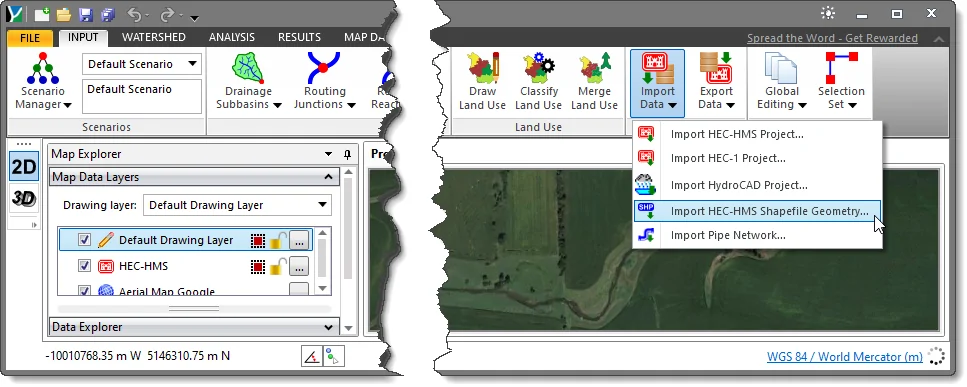
- The Import HEC-HMS Shapefile Geometry dialog box will be displayed.
The following sections describe the Import HEC-HMS Shapefile Geometry command and how to interact with the above dialog box.
Subbasin Data
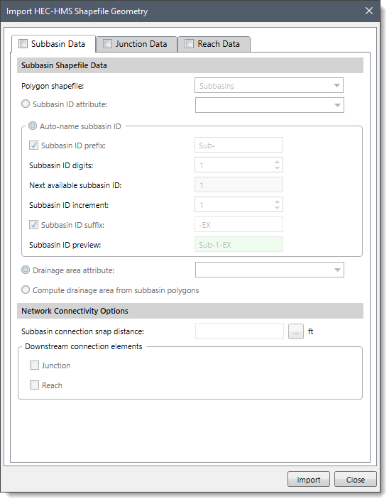
The Subbasin Data tabbed panel allows the user to import the subbasin geometry using the polygon shapefile, which can be used to define the GeoHECHMS subbasin elements. By default, the content of this panel is disabled (i.e., grayed out). Select the Subbasin Data checkbox to enable the content of this panel. Note that the subbasin shapefile should be loaded before using this panel. Otherwise, no geometry will be imported.
Subbasin Shapefile Data
This section allows the user to define the subbasin data:
- Polygon shapefile
This dropdown combo box allows the user to select the subbasin shapefile to be imported into the model. The dropdown combo box lists only polygon shapefiles.
- Subbasin ID attribute
This option allows the user to define the subbasin ID using the subbasin attributes defined in the shapefile data. The user can select the attributes from the dropdown combo box provided next to this option. This dropdown combo box lists only those attributes that contain text.
- Auto-name subbasin ID
This radio button option allows the user to automatically specify the ID for each subbasin. The user can assign these IDs using a predefined format or by manually defining the format of the ID. The different subbasin naming formats present in the Auto-name subbasin ID option are as follows:
- Subbasin ID prefix: This option allows a prefix to be added to the front of the subbasin ID.
- Subbasin ID digits: This option permits specification of a set number of digits to use for the subbasin ID. For example, using 3 digits causes the subbasin ID to be of the format 001, 002, etc.
- Next available subbasin ID: This entry defines the next element ID number to be used.
- Subbasin ID increment: This entry defines the increment to use when numbering elements. The default value is 1.
- Subbasin ID suffix: This option allows a suffix to be added to the end of the subbasin ID.
- Subbasin ID preview: This entry provides a preview of the subbasin naming specifications defined above.
- Drainage area attribute
This option allows the user to define the subbasin area using the subbasin attributes defined in the shapefile data. The user can select the attributes from the dropdown combo box provided next to this option. This dropdown combo box lists only those attributes that contain numeric values.
- Compute drainage area from subbasin polygons
This option causes the software to automatically compute the drainage area based upon the subbasin polygon area.
Network Connectivity Options
This section allows the user to specify the network connectivity for the subbasin.
- Subbasin connection snap distance
This entry field is used to specify the subbasin connection snap distance. Alternatively, the user can click the […] button to measure the snap distance from the Map View. This snapping distance (i.e., radial distance) is used by the software to automatically snap the subbasin to the nearest junction or reach elements within this set distance or range.
- Downstream connection elements
This subsection allows the user to select the downstream element within the set snap distance that the selected subbasin drains to. The following elements can be selected:
- Junction
- Reach
If there are more than one downstream element, the software will analyze each element’s location and compare it to the set snap distance. The software will then determine which element has the nearest location to the subbasin and assign that element as the downstream connection element.
Note that if the user does not specify the snap distance, then the software will automatically find the selected elements nearest to the subbasin center point and assign them as the downstream connection elements.
Junction Data
The Junction Data tabbed panel allows the user to import the junction geometry using the node shapefile, which can be used to define the GeoHECHMS junction elements. By default, the content of this panel is disabled (i.e., grayed out). Select the Junction Data checkbox to enable the content of this panel. Note that the junction shapefile should be loaded before using this panel. Otherwise, no geometry will be imported.
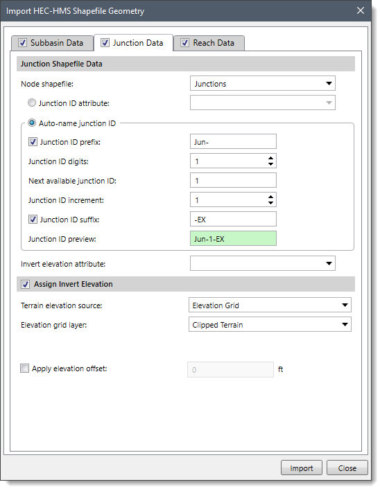
Junction Shapefile Data
This section allows the user to define the junction data.
- Node shapefile
This dropdown combo box allows the user to select the junction shapefile to be imported into the model. The dropdown combo box lists only node shapefiles.
- Junction ID attribute
This option allows the user to define the junction ID using the junction attributes defined in the shapefile data. The user can select the attributes from the dropdown combo box provided next to this option. This dropdown combo box lists only those attributes that contain text.
- Auto-name junction ID
This radio button option allows the user to automatically specify the ID for each junction. The user can assign these IDs using a predefined format or manually define the format of the ID. Note that the different junction naming formats available through this option are similar to the Auto-name subbasin ID option of the Subbasin Shapefile Data.
- Invert elevation attribute
This dropdown combo box allows the user to select the junction invert elevation using the junction attributes defined in the shapefile data. The dropdown combo box lists only those attributes that contain numeric values.
Assign Invert Elevation
This optional section allows the user to assign an invert elevation to the junction using a terrain model.
To assign an invert elevation, the Terrain elevation source dropdown combo box supports the following surface types:
- Elevation grids
- LandXML data
- TIN surfaces
The user can also apply an elevation offset by checking the Apply elevation offset checkbox. On selecting this checkbox, the entry field next to it becomes available for entering an elevation offset value. The user can define a negative offset value to lower the junction for specific circumstances—for example, defining a manhole bottom elevation.
Reach Data
The Reach Data tabbed panel allows the user to import the reach geometry using the stream (polyline) shapefile, which can be used to define the GeoHECHMS reach elements. By default, the content of this panel is disabled (i.e., grayed out). Select the Reach Data checkbox to enable the content of this panel. Note that the reach shapefile should be loaded before using this panel. Otherwise, no geometry will be imported.
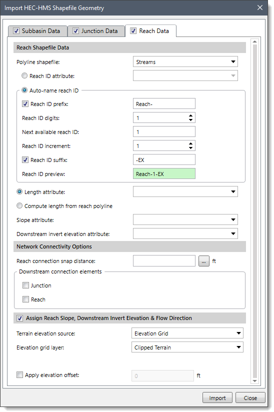
Reach Shapefile Data
This section allows the user to define the reach data.
- Polyline shapefile
This dropdown combo box allows the user to select the reach shapefile to be imported into the model. The dropdown combo box lists only stream (polyline) shapefiles.
- Reach ID attribute
This option allows the user to define the reach ID using the reach attributes defined in the shapefile data. The user can select the attributes from the dropdown combo box provided next to this option. This dropdown combo box lists only those attributes that contain text.
- Auto-name reach ID
This radio button option allows the user to automatically specify the ID for each reach. The user can assign these IDs using some predefined format or by manually defining the format of the ID. Note that the different reach naming formats present in this option are similar to the Auto-name subbasin ID option of the Subbasin Shapefile Data.
- Length attribute
This option allows the user to define the reach length using the reach attributes defined in the shapefile data. The user can select the attributes from the dropdown combo box provided next to this option. This dropdown combo box lists only those attributes that contain numeric values.
- Compute length from reach polyline
This option causes the software to automatically compute the reach length based upon the reach polyline length.
- Slope attribute
This dropdown combo box allows the user to select the slope of the reach using the reach attributes defined in the shapefile data. The dropdown combo box lists only those attributes that contain numeric values.
- Downstream invert elevation attribute
This dropdown combo box allows the user to select the downstream invert elevation using the reach attributes defined in the shapefile data. The dropdown combo box lists only those attributes that contain numeric values.
Network Connectivity Options
This section allows the user to specify the network connectivity for the reach.
- Reach connection snap distance
This entry field is used to specify the reach connection snap distance. Alternatively, the user can click the […] button to measure the snap distance from the Map View. This snapping distance (i.e., radial distance) is used by the software to automatically snap the reach to the nearest junction or reach elements within this set distance or range.
- Downstream connection elements
This subsection allows the user to select the downstream element within the set snap distance that the selected reach drains to. The following elements can be selected:
- Junction
- Reach
If there is more than one downstream element, the software will analyze each element’s location and compare it to the set snap distance. The software will then determine which element has the nearest location to the reach and assign that element as the downstream connection element.
Notes:
- If the user does not specify the snap distance, then the software will automatically find the selected element nearest to the reach and assign that element as the downstream connection element.
- A reach can connect downstream to another reach. Multiple reaches can be chained together to represent a long river reach with changing geometry. However, a reach cannot connect downstream to a subbasin.
Assign Reach Slope, Downstream Invert Elevation & Flow Direction
This optional section allows the user to assign the reach slope, invert elevations, and river flow direction (upstream to downstream) to the reach using a terrain model.
The options provided in this section are similar to the Assign Invert Elevation section of the Junction Data panel explained above in the article.
When all the options have been properly defined, click the [Import] button to import HEC-HMS shapefile geometry. After the HEC-HMS shapefile geometry is imported, the extent of the model will be displayed in the Map View.


