The pipe network in AutoCAD Civil 3D consists of varying sizes of pipes, structures, or both pipes and structures. A pipe network is used to manage a collection of pipes and structures that are associated with each other to represent a pipe system.
The pipe network comprises the following components:
- Pipe: Pipes are structures or links that convey water from one point in the network to another. It is used in utility networks, such as sewer and irrigation systems. In a drawing, the pipe is defined by the shape (circular, elliptical, egg-shaped, or rectangular) and a path (linear or curved).
- Structure: A structure is a drawing shape that represents manholes, catch basins, and headwalls. Its shape is inherently more complex than pipe shape.
- Null Structure: It is a special type of structure that is inserted automatically when a pipe is directly connected to another pipe without any structure shape between the two pipes.
The drawing of a pipe network also contains parcels used to describe a property or a spatial area that is defined by boundary edges.
In GeoHECHMS, the user can import the pipe and manhole network created in AutoCAD Civil 3D using the Import Pipe Network command. This command imports pipe and manhole networks using a LandXML file.
The following list details the conversions that will occur when importing a pipe network model:
- The pipes are imported as reaches with the same lengths, diameters, and slopes. Note that the pipe (linear or curved) represented in a reach will always be a straight line. The length and slope of the pipe will become the reach length and slope.
- The shape of the reach is always circular, and the flow direction is higher elevation to lower elevation. The pipe end with the lower elevation will be the downstream end of the reach.
- The pipe diameter and roughness will become the reach diameter and roughness.
- The manholes are imported as junctions. The junction will be placed at the end point of each pipe. Each junction will have an invert elevation.
- If the LandXML file does not contain any junction data, a dummy junction (null structure) is inserted automatically. The dummy junction will have an invert elevation equal to the next downstream pipe’s upstream end invert elevation.
- The parcels (drainage areas) are imported as subbasins. These subbasins will not inherit any attributes from AutoCAD Civil 3D. The software just uses the parcels’ geometry and specifies the default values.
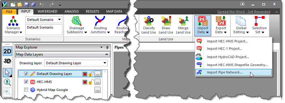
Follow the steps below to use the Import Pipe Network command:
- From the Input ribbon menu, click the Import Data dropdown menu and then select the Import Pipe Network command.
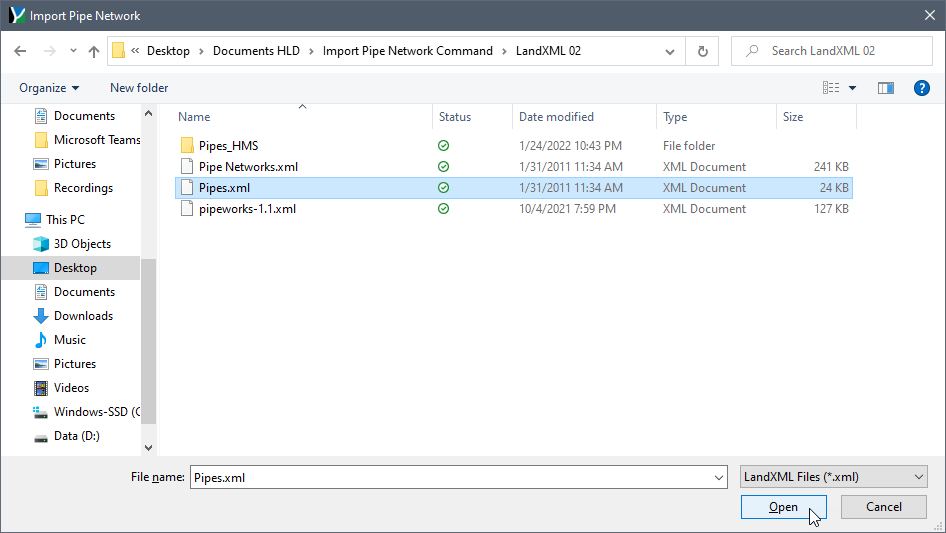
- The Import Pipe Network file open dialog box will be displayed. This dialog box allows the user to browse to the location where the LandXML file is located.
- Select the LandXML file (it will have a file extension of .xml) and click the [Open] button.
- The software will then import the LandXML data and create a network model from this data, as shown below.
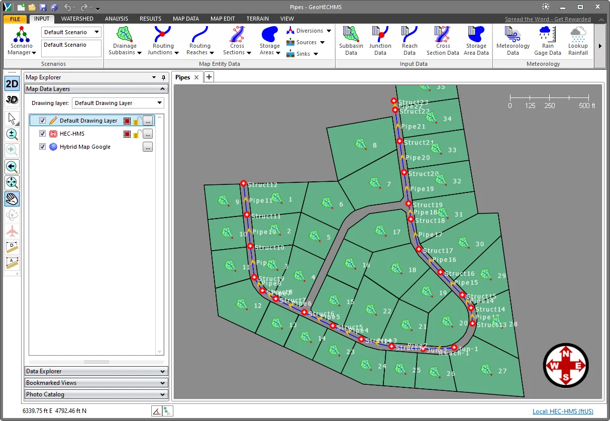
- After importing the pipe network, the user can make changes to the network model such as pipe sizes, inverts elevations, etc. to get a working model.
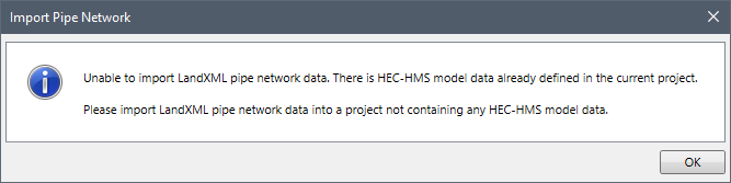
Note that when this command is selected, the software first checks to see if there is any HEC-HMS data already loaded. If the software finds any HEC-HMS model data in the current project, the following informational dialog box will be displayed.