
Welcome to CivilGEO Knowledge Base
Welcome to CivilGEO Knowledge Base
Creating a HEC-RAS 2D mesh that correctly represents the flow area being modeled can take some time due to the need to add the appropriate details to the model to represent the components and due to the terrain data to be included.
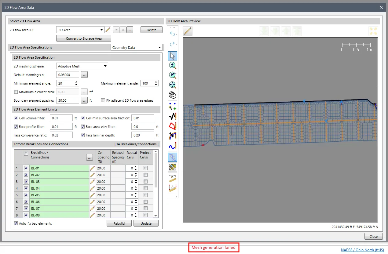
When working with complex meshes, there may be times when the mesh generation fails to run. When this situation occurs, the user will need to review the data that has been assigned to construct the mesh.
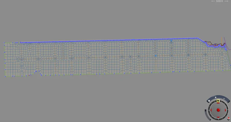
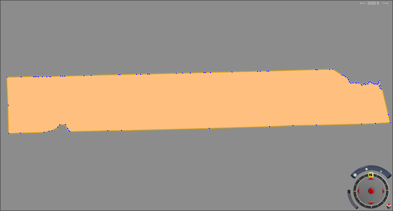
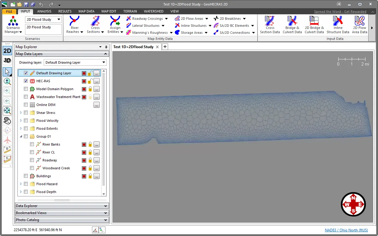
For example, the below 2D mesh fails to correctly generate an adaptive mesh.
However, upon review of the polygon boundary used to define the mesh, it becomes evident that the upper boundary contains a large number of unnecessary and redundant vertices.
In this situation, the Simplify Elements command of the Map Edit ribbon menu can be used to correct this issue by removing the redundant vertices along the 2D mesh boundary.
The following sections describe how to perform this task.
To be able to simplify the 2D flow area mesh boundary, it needs to be exported as a shapefile. Follow the steps below:
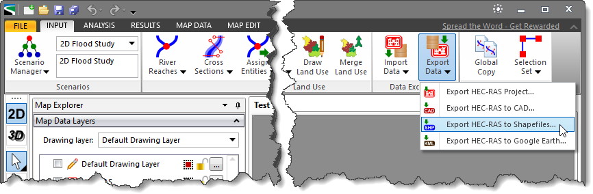
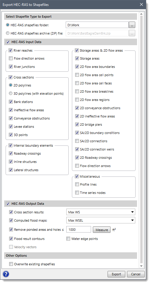 The Export HEC-RAS to Shapefiles dialog box is used to export a HEC-RAS model to GIS shapefiles allowing the HEC-RAS model data to be shared with GIS software. Refer to this article in our knowledge base for further discussion on how to export the HEC-RAS elements.
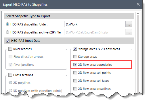
![[Export] button](/wp-content/uploads/sites/25/2019/02/Export-HEC-RAS-to-Shapefiles-Image-6-.png)
Next, we need to import the polygon shapefile that was exported. Follow the steps below to import the polygon shapefile.
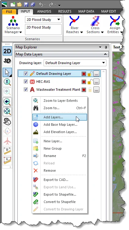
![Add Layers - [Open] button](/wp-content/uploads/sites/25/2019/02/Export-HEC-RAS-to-Shapefiles-Image-8.png)
The imported polygon shapefile will be used to recreate the 2D flow area for the HEC-RAS model. However, the number of vertices that define the shapefile polygon first needs to be simplified. For this, the Simplify Elements command can be used. Refer to this article in our knowledge base to learn how to use the Simplify Elements command.
Upon using the Simplify Elements command, the polygon will be simplified, reducing the number of redundant vertices used to describe the polygon boundary.
After simplifying the polygon, it can be used to define the 2D mesh. In HEC-RAS, generation of the 2D mesh for 2D modeling begins with the 2D flow area. The 2D flow area defines the boundary for which the computation will occur. The user can use the Assign 2D Flow Areas command for assigning the simplified polygon as a 2D flow area. Refer to this article in our knowledge base to learn how to use the Assign 2D Flow Areas command.
After the 2D flow area polygon boundary is created, the next step is to begin generating the 2D mesh. Follow the steps below to generate the 2D mesh:
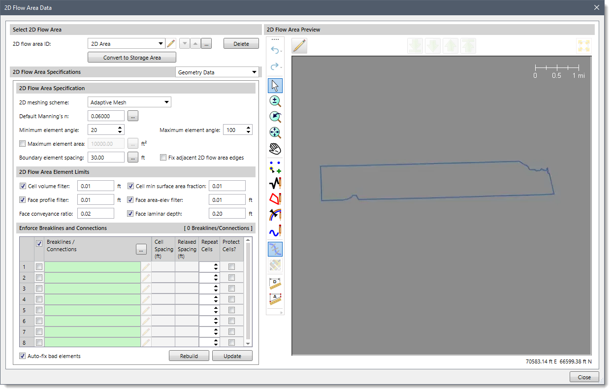
![[Update] button](/wp-content/uploads/sites/25/2019/02/Export-HEC-RAS-to-Shapefiles-Image-11.png)


CivilGEO G2 Reviews
4.8/5.0 Rating, Over 230 Reviews

GeoHECRAS is recognized as the top Civil Engineering Design Software with an average of 4.8 out of 5.0 rating from over 230 real user reviews on G2.


We use cookies to give you the best online experience. By agreeing you accept the use of cookies in accordance with our cookie policy.
When you visit any web site, it may store or retrieve information on your browser, mostly in the form of cookies. Control your personal Cookie Services here.


