
Welcome to CivilGEO Knowledge Base
Welcome to CivilGEO Knowledge Base
The GIS Element Properties dialog box allows the user to define various GIS elements and their properties, style the border associated with the element, and change the image’s transparency. Furthermore, it also allows the user to change the CRS (coordinate reference system) of the current project and automatically apply the transformation scale factor to any layer to accurately map it to the project CRS.
Following are the types of GIS Element Properties dialog boxes for the GIS elements: polygons, polylines, and points, respectively:
In this article, we will use the GIS Polygon Properties dialog box to demonstrate and describe the GIS Element Properties dialog box of the CivilGEO software.
Follow the steps below to use the GIS Polygon Properties dialog box:
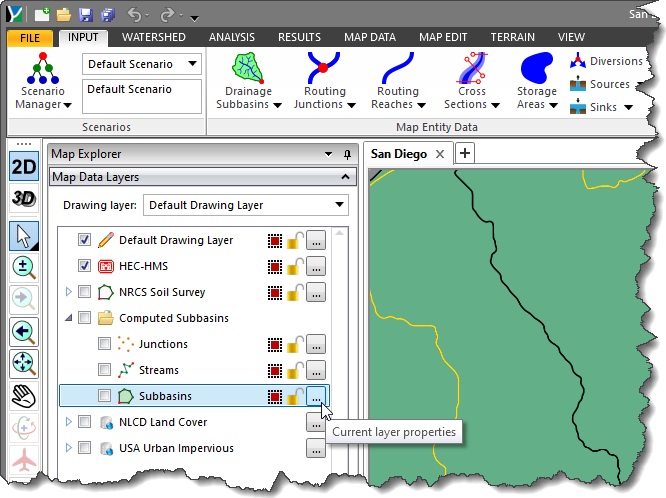 Note that the user must follow the same step to access the GIS Element Properties dialog box for the other GIS element types, such as point and polyline.
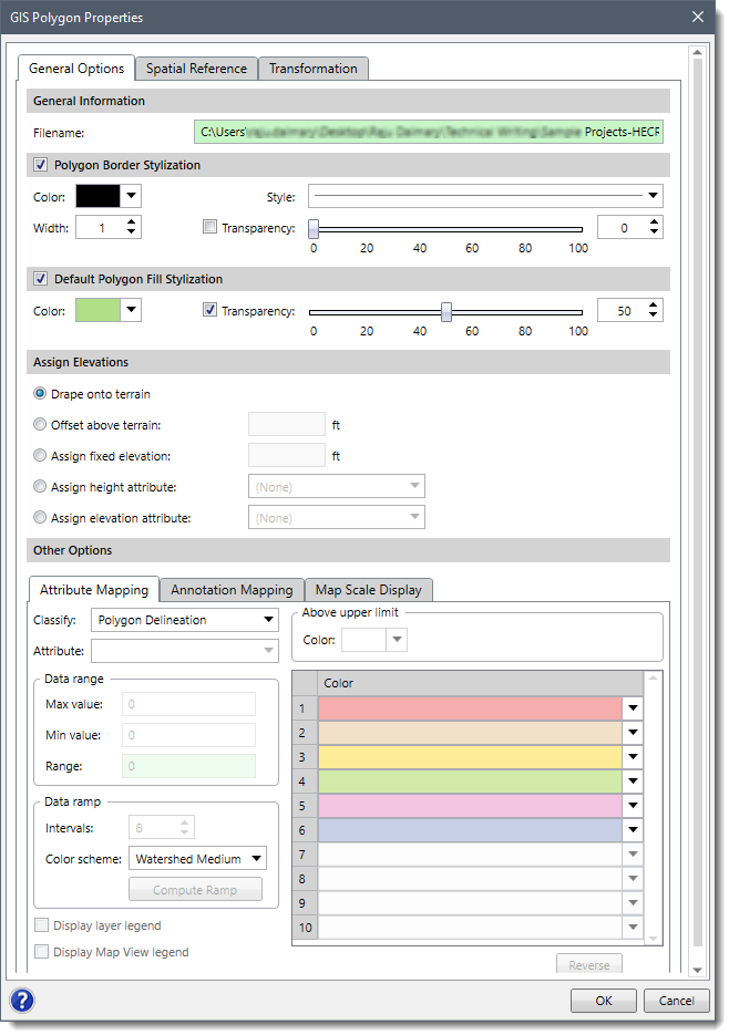
The GIS Polygon Properties dialog box contains three tabs as described below:
Various sections of the General Options tab are described below:
This section contains read-only information about the location of the element properties file and the file name.
This section is associated with the border of the polygon. It allows the user to set its color, width, style, and transparency. Note that the Polygon Border Stylization checkbox is selected by default.
This section provides options for the user to fill the polygon with color and adjust the transparency so that you can see through the polygon to the background Base Map. A transparency value of 40 to 50% works well. Note that the Default Polygon Fill Stylization checkbox is selected by default.
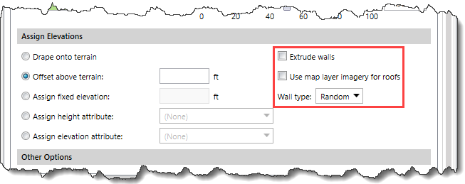
This section is used to assign elevation to elements. The following radio button options are available:
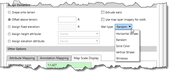
In addition, the following options are available in this section. Note that these options are available only when the user has selected an option other than the Drape onto terrain option.
This section is divided into the following three panels:
The Spatial Reference tab allows the user to manually assign the project’s CRS to the non-CRS referenced data layer coordinates if the data layer lies within the project’s CRS. Refer to this article in our knowledge base to learn more about spatial reference.
The Transformation tab allows the user to automatically apply the transformation scale factor to any particular layer and accurately map it to the project coordinate reference system (CRS). Refer to this article in our knowledge base to learn more about layer transformation.


CivilGEO G2 Reviews
4.8/5.0 Rating, Over 230 Reviews

GeoHECRAS is recognized as the top Civil Engineering Design Software with an average of 4.8 out of 5.0 rating from over 230 real user reviews on G2.


We use cookies to give you the best online experience. By agreeing you accept the use of cookies in accordance with our cookie policy.
When you visit any web site, it may store or retrieve information on your browser, mostly in the form of cookies. Control your personal Cookie Services here.


