
Welcome to CivilGEO Knowledge Base
Welcome to CivilGEO Knowledge Base
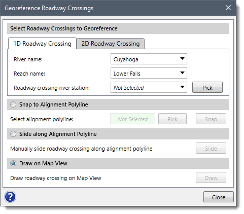
The Georeference Roadway Crossings command allows the user to automatically map roadway crossings to the desired locations by snapping, sliding, or by drawing an alignment polyline on the Map View. This command can also be used to georeference an existing roadway crossing and generate more accurate calculations.
The following options are available for georeferencing roadway crossings:
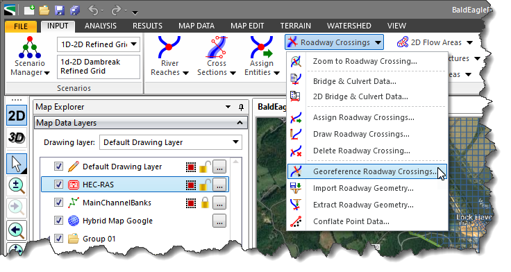
Follow the steps given below to use the Georeference Roadway Crossings command:
The following sections describe how to georeference a roadway crossing and interact with the above dialog box.
The Select Roadway Crossings to Georeference section allows the user to interactively select the roadway crossings in order to georeference them on the Map View. It contains two panels:
Note that if the model contains only 2D elements, then the 1D Roadway Crossing panel will be disabled.
The 1D Roadway Crossing panel allows the user to select the river, corresponding reach, and the roadway crossing river station from the River name, Reach name, and Roadway crossing river station dropdown combo boxes. Alternatively, the user can click the [Pick] button to select the roadway crossing river station from the Map View.
The 2D Roadway Crossing panel allows the user to select the 2D roadway crossing from the 2D roadway crossing ID dropdown combo box. Alternatively, the user can click the [Pick] button to select the 2D roadway crossing from the Map View.
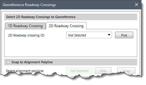
After selecting the roadway crossing, the user can use one of the following options to georeference it.
This option allows the user to snap a roadway crossing to an existing alignment polyline on the Map View.
Follow the steps below to use the Snap to Alignment Polyline option:
![[Pick] button](/wp-content/uploads/sites/25/2022/06/Georeferencing-Roadway-Crossings-Image-4.png)
![[Snap] button](/wp-content/uploads/sites/25/2022/06/Georeferencing-Roadway-Crossings-Image-5.png)
This option allows the user to manually slide the roadway crossing along the alignment polyline.
Follow the steps below to use the Slide along Alignment Polyline option:
![[Slide] button](/wp-content/uploads/sites/25/2022/06/Georeferencing-Roadway-Crossings-Image-6.png)
Notes:
This option allows the user to draw an alignment polyline and automatically snap the selected roadway crossing to the drawn polyline.
Follow the steps below to use the Draw on Map View option:
![[Draw] button](/wp-content/uploads/sites/25/2022/06/Georeferencing-Roadway-Crossings-Image-7.png)


CivilGEO G2 Reviews
4.8/5.0 Rating, Over 230 Reviews

GeoHECRAS is recognized as the top Civil Engineering Design Software with an average of 4.8 out of 5.0 rating from over 230 real user reviews on G2.


We use cookies to give you the best online experience. By agreeing you accept the use of cookies in accordance with our cookie policy.
When you visit any web site, it may store or retrieve information on your browser, mostly in the form of cookies. Control your personal Cookie Services here.


