
Welcome to CivilGEO Knowledge Base
Welcome to CivilGEO Knowledge Base
When the software imports a model, it automatically places the reaches on the Map View. However, if the original model was not spatially georeferenced, the reaches will not align with any loaded background base map. While the software can operate without any issues in this situation, the user may prefer that the reaches be georeferenced to the background base map. Therefore, it may become necessary to georeference the imported reaches.
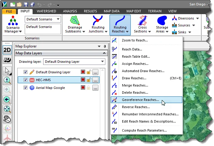
The Georeference Reaches command in GeoHECHMS software is used to manually georeference each of the reaches to the background base map displayed in the Map View. The process of georeferencing a reach to the Map View can be a trial-and-error process, especially when the exact location of the original reach is not known. Using the Georeference Reaches command, this process is accelerated.
Follow the steps below to georeference an existing reach:
The following sections describe how to georeference an existing reach and interact with the above dialog box.
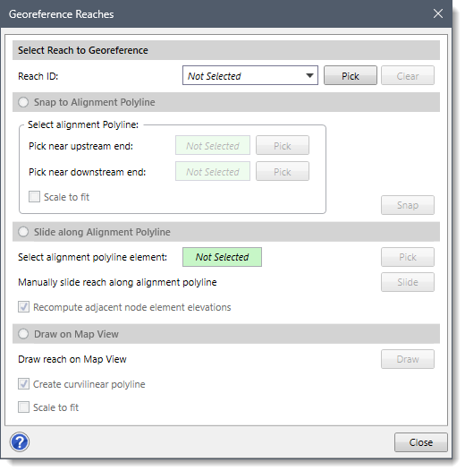
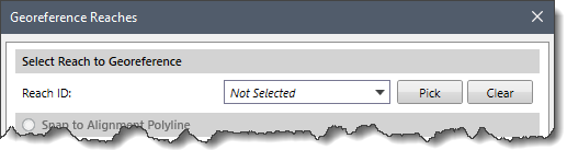
The Select Reach to Georeference section allows the user to select the reach to be georeferenced.
Note that if a reach has been preselected from the Map View before running this command, then the selected reach will be displayed in the Reach ID dropdown combo box.
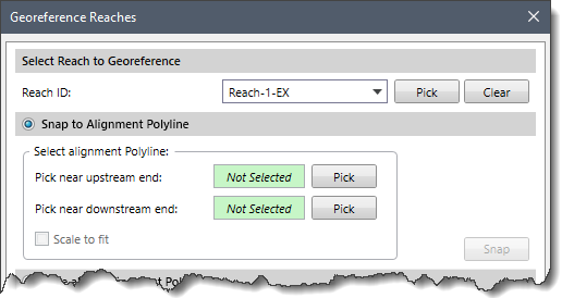
If the model contains a single reach, then it will automatically be selected in the Reach ID dropdown combo box. If the model contains multiple reaches, then the user can select the desired reach from the Reach ID dropdown combo box.
Alternatively, the user can click the [Pick] button to select the reach from the Map View. Clicking on the [Pick] button causes the dialog box to temporarily disappear, and the user will be prompted to select the reach from the Map View. After selecting a reach, the dialog box will be redisplayed with the reach shown as selected. The selected reach will also be highlighted on the Map View.
Note that the user can click the [Clear] button to cancel all the previous selections and redo the entire process.
After selecting the reach, the user can select one of the following georeference options:
If an existing alignment polyline for the selected reach exists on the Map View, the Snap to Alignment Polyline section can be used to snap the reach to the alignment polyline. Selecting the Snap to Alignment Polyline radio button option enables this section.
This section contains the following options:
After selecting the upstream and downstream end of the reach, click the [Snap] button and the reach will get snapped to the alignment polyline.
Note that the [Snap] button can only be enabled when the upstream and downstream ends of the reach have been selected. In addition, a preview of the snapped reach is shown on the alignment polyline, which allows the user to reselect the downstream and upstream points or cancel the selection process.
The user can turn on the Scale to fit checkbox option to scale the reach to fit within the alignment polyline.
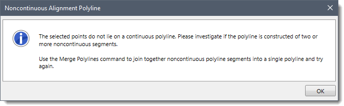
If the upstream and downstream points do not overlay the same continuous alignment polyline, then the following informational message will be displayed.
If the reach has been snapped to an alignment polyline on the Map View, but is not precisely located where it should be, the Slide along Alignment Polyline section can be used to slide the reach along the alignment polyline. Selecting the Slide along Alignment Polyline radio button option enables this section.
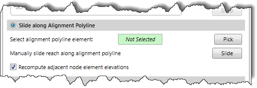
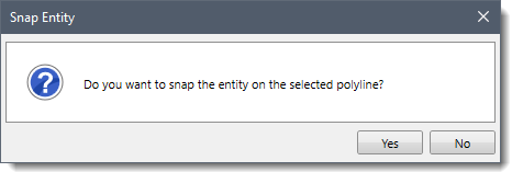
Clicking the [Pick] button allows the user to select an alignment polyline from the Map View. On clicking the [Pick] button, the dialog box will temporarily disappear, and the user will be prompted to select an alignment polyline. After selecting the alignment polyline, a Snap Entity dialog box will be displayed. Click the [Yes] button to snap the entity on the selected polyline. Otherwise, click the [No] button to cancel the selection and redo the entire process.
After selecting the alignment polyline, the Georeference Reaches dialog box will be redisplayed and the Select alignment polyline element read-only entry will change from Not Selected to Selected.
Click the [Slide] button to manually slide the reach along the underlying alignment polyline. Clicking the [Slide] button makes the dialog box temporarily disappear and prompts the user to select the reach and drag it along the underlying alignment polyline. Once finished, press the [Enter] key or right-click and select Done from the displayed context menu. To abort the slide operation, press the [Esc] key and the moved reach will return to its original location.
While sliding the reach along the alignment polyline, the user would not be allowed to move the reach beyond the end of the alignment polyline. The Recompute adjacent node element elevations checkbox option allows the user to recompute the elevation of the adjacent node type elements after georeferencing the reach.
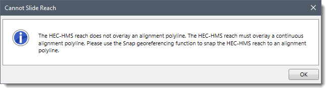
Note that if the endpoints of the reach do not overlay the same continuous polyline, then the following informational message will be displayed.
This section allows the user to draw the reach on the Map View. Selecting the Draw on Map View radio button option enables this section.
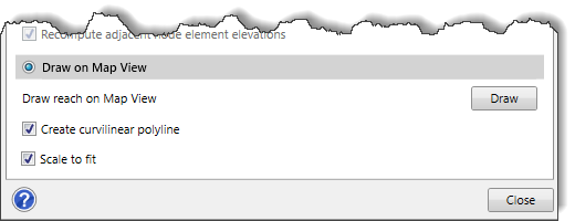
Clicking the [Draw] button temporarily removes the dialog box and prompts the user to draw the reach on the Map View. Once the reach is drawn, press the [Enter] key or right-click and select Done from the displayed context menu. The reach will then automatically snap to the drawn alignment polyline.
The user can turn on the Create curvilinear polyline checkbox option to draw the polyline using a curvilinear segment. Refer to this article in our knowledge base to learn more about element digitizing on the Map View.
The user can turn on the Scale to fit checkbox option to scale the reach to fit within the alignment polyline.


CivilGEO G2 Reviews
4.8/5.0 Rating, Over 230 Reviews

GeoHECRAS is recognized as the top Civil Engineering Design Software with an average of 4.8 out of 5.0 rating from over 230 real user reviews on G2.


We use cookies to give you the best online experience. By agreeing you accept the use of cookies in accordance with our cookie policy.
When you visit any web site, it may store or retrieve information on your browser, mostly in the form of cookies. Control your personal Cookie Services here.


