
Welcome to CivilGEO Knowledge Base
Welcome to CivilGEO Knowledge Base
When the GeoHECHMS software imports a model, it automatically places the cross sections on the Map View. However, if the original model was not spatially georeferenced, the cross sections will not align with any loaded background base map. While the software can operate without any issues in this situation, it is preferable to have the cross sections georeferenced to the background base map. Therefore, it might become necessary to georeference the imported cross sections.
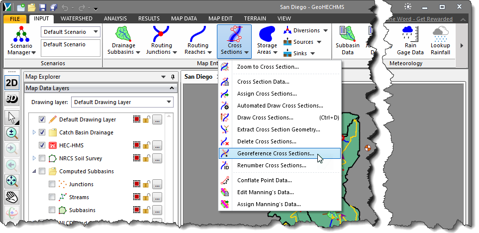
The Georeference Cross Sections command of the GeoHECHMS software can be used to manually georeference each of the cross sections to the background base map displayed in the Map View. The process of georeferencing a cross section to the Map View can be a trial and error process—especially when the exact location of the original cross section is not known. Using the Georeference Cross Sections command, this process is accelerated.
Note that a CRS should be assigned prior to running this command. Otherwise, the software will display the below informational dialog box.
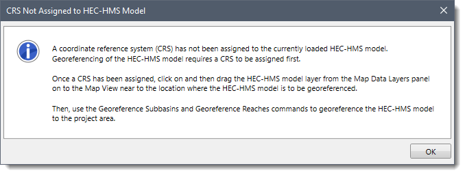
Refer to this article in our knowledge base to learn how to assign a coordinate reference system to a project.
Follow the steps below to georeference an existing cross section in GeoHECHMS:
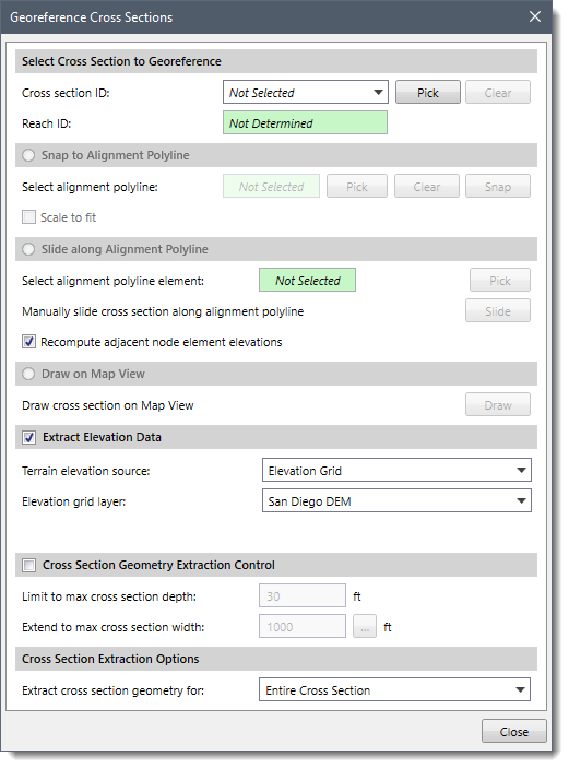
The following sections describe how to georeference an existing cross section and interact with the above dialog box.
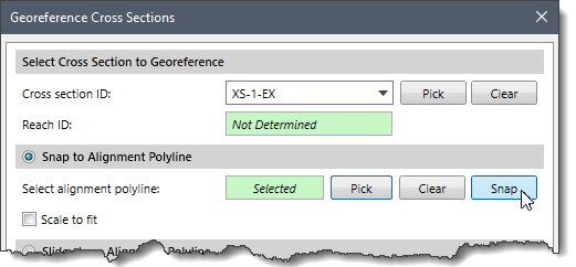
The Select Cross Section to Georeference section allows the user to interactively select the cross section to georeference on the Map View. The user can either select the cross section from the Cross Section ID dropdown combo box or click the [Pick] button to select the cross section from the Map View. Once the cross section is selected, the reach associated with the selected cross section will be displayed in Reach ID read-only field.
Note that the user can click the [Clear] button to cancel the previous selection and redo the entire process.
Once the cross section has been selected, the user can choose between the following options to georeference the cross section:
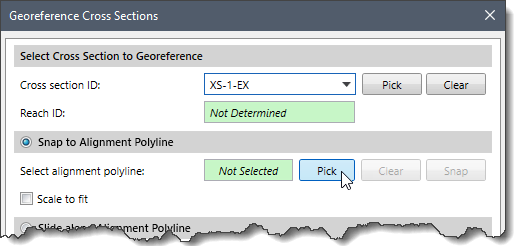
If an existing alignment polyline for the cross section exists on the Map View, the Snap to Alignment Polyline option can be used to snap the cross section to the alignment polyline.
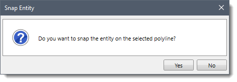
Follow the steps below to use the Snap to Alignment Polyline option:
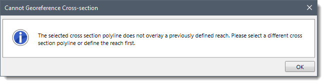
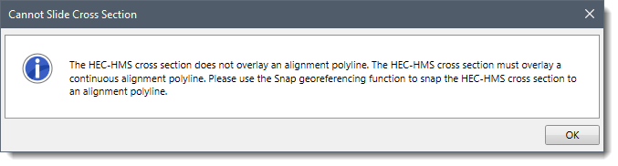
Note that if the selected cross section polyline does not overlay the previously defined reach, the following informational dialog box will be displayed.
This option allows the user to manually slide the cross section along the alignment polyline.
Follow the steps below to use the Slide along Alignment Polyline option:
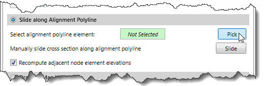
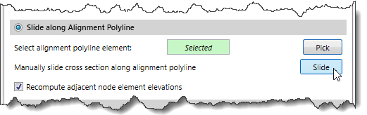
Note: For more precision, the user can use the Snap to Alignment Polyline option first and then use the Slide along Alignment Polyline option.
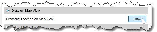
This option allows the user to draw an alignment polyline and automatically snap the selected cross section to the drawn polyline.
Follow the steps below to use the Draw on Map View option:
This optional section is used to define the elevation data source to be used for extracting the cross section geometry. Depending upon the elevation data source type that is selected, different options are provided to specify additional elevation data information.
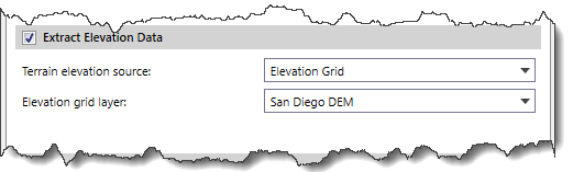
Refer to this article in our knowledge base for information on the types of terrain elevation data that can be used for constructing cross sections.
Note that if the Extract Elevation Data checkbox is unchecked, then the options under the subsequent sections will be unavailable (i.e., grayed out).
This optional section is used to control the amount of cross section geometry to extract for the drawn cross section polylines. This assures that an adequately deep enough cross section is created on both sides of the reach. The software will attempt to retrieve the cross section geometry data to the depth specified within the specified maximum cross section width.
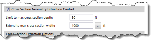
If the drawn polyline does not extend outward far enough to get the cross section depth specified, the software will automatically extend the constructed cross section further outward. Similarly, if the drawn polyline extends too far outward for the depth specified, the software will automatically trim the constructed cross section.
This section is used to control which portions of the cross section(s) should be extracted.
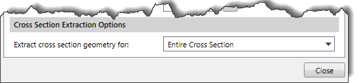
For example, the user may have survey data for the cross section channel and a LIDAR digital terrain surface for the overbank areas. In this example, the user would only want to extract the cross section geometry for the overbank areas since the surveyed channel geometry is already accurate.
The Extract cross section geometry for dropdown combo box contains the following entries:


CivilGEO G2 Reviews
4.8/5.0 Rating, Over 230 Reviews

GeoHECRAS is recognized as the top Civil Engineering Design Software with an average of 4.8 out of 5.0 rating from over 230 real user reviews on G2.


We use cookies to give you the best online experience. By agreeing you accept the use of cookies in accordance with our cookie policy.
When you visit any web site, it may store or retrieve information on your browser, mostly in the form of cookies. Control your personal Cookie Services here.


