
Welcome to CivilGEO Knowledge Base
Welcome to CivilGEO Knowledge Base
Digital terrain surfaces can be used for the following tasks:
While the software can read in a variety of terrain surface types, it is sometimes necessary to construct a terrain surface from newly acquired elevation data. This section describes how to do that.
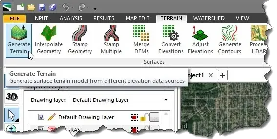
 The following sections describe the Generate Terrain command and how to interact with the above dialog box.
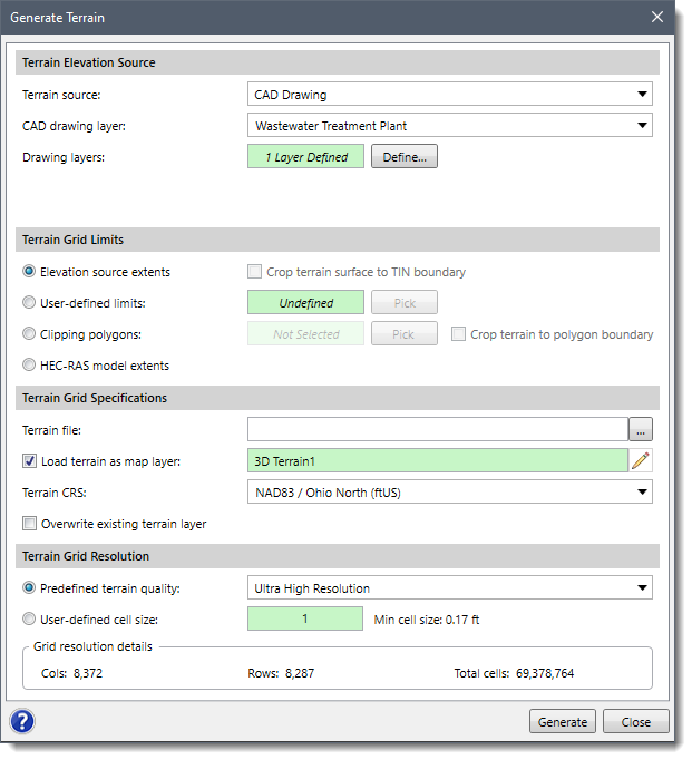
This section controls the selection of the elevation data source to be used for generating the terrain surface. If a map data layer was selected prior to selecting this command, the map data layer will be already selected within this section.
From the Terrain source entry, select the terrain source type to be used for generating the terrain surface. The following terrain source types are supported:
Based upon the terrain source type selected, additional fields are provided for selecting the map data layer and attribute information.
The terrain surface that is constructed using this command is a rectangular grid. The user can define the rectangular extents of the constructed terrain surface to an area of interest. The following options are available for defining the rectangular extents of the generated terrain surface:
By default, the Crop terrain surface to TIN boundary option is checked if the user selects TIN surface or LandXML Data from the Terrain source entry. The generated terrain surface grid will not extend outside of the TIN boundary.
This section is used to define the specifications for the generated terrain surface.
Click the […] button for the Terrain file entry to specify the file name and directory location to save the generated terrain grid file.
By default, the Load terrain as map layer checkbox option is checked to load the terrain file as a layer in the Map Data Layers panel. Click the pencil icon to rename the layer.
The user can select the CRS to be used for the generated terrain grid. If there is only one CRS being used in the project, the software automatically selects it.
By default, the Overwrite existing terrain layer checkbox option is checked. This option controls overwriting an existing terrain layer with the same layer name.
This section is used to define the terrain quality and the cell size for the terrain grid being generated.
From the Predefined terrain quality entry, choose the resolution option to be used. Elevation grid resolutions range from low to ultra-high quality for the terrain surface grid being generated.
From the User-defined cell size entry, the user can manually define the elevation grid cell size. The finer the grid resolution (or smaller the cell size) defined, the greater the detail that can be represented in the generated terrain surface. However, a smaller cell size results in more cells generated for the grid, creating a larger grid file and taking longer to generate.
After the options have been defined, click the [Generate] button and the software will create the elevation grid file and load the grid as a new layer in the Map Data Layers panel.


CivilGEO G2 Reviews
4.8/5.0 Rating, Over 230 Reviews

GeoHECRAS is recognized as the top Civil Engineering Design Software with an average of 4.8 out of 5.0 rating from over 230 real user reviews on G2.


We use cookies to give you the best online experience. By agreeing you accept the use of cookies in accordance with our cookie policy.
When you visit any web site, it may store or retrieve information on your browser, mostly in the form of cookies. Control your personal Cookie Services here.


