
Welcome to CivilGEO Knowledge Base
Welcome to CivilGEO Knowledge Base
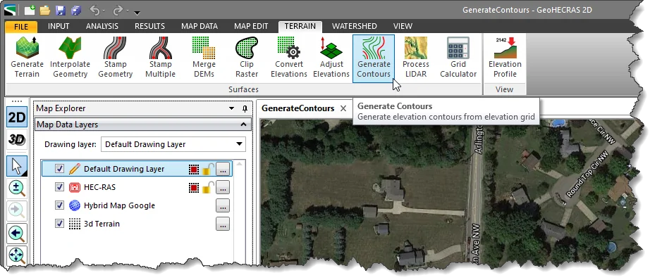
The Generate Contours command creates equally spaced contour lines from loaded elevation grid data. The user can specify major and minor contour line spacing, line weight, line colors, and more. Elevation contours help the user decide where to place cross sections on the Map View to capture the flow area most effectively as the flow travels downstream.
Follow the steps below to generate contours:
The following sections describe the Generate Contours command and how to interact with the above dialog box.
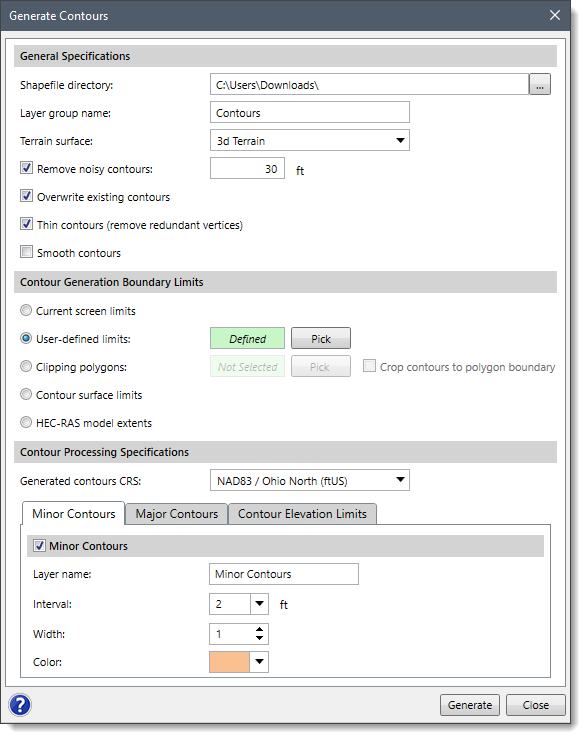
This section describes how to save the generated contours shapefiles and controls the selection of DEMs for contour generation from the available loaded elevation grids.
Click the […] button from the Shapefile directory entry to specify the directory location to store the generated contour shapefiles.
By default, the Layer group name is Contours and it can be changed by the user.
From the Terrain surface entry, select the DEM layer from which the contours are to be generated.
The Remove noisy contours checkbox allows the software to remove the contour layers whose elevation lies outside the range specified by the user.
The Overwriting existing contours checkbox allows the software to overwrite an existing contour layer with the same layer name.
The Thin contours (remove redundant vertices) checkbox removes redundant vertices that do not contribute to the shape of the generated contour polylines.
The Smooth contours option controls whether extra vertices are added along the contour polyline to improve their appearance.
The user can define the rectangular extents along which the contours are to be generated. The following options are available for defining the rectangular extents of the elevation grid:
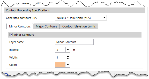
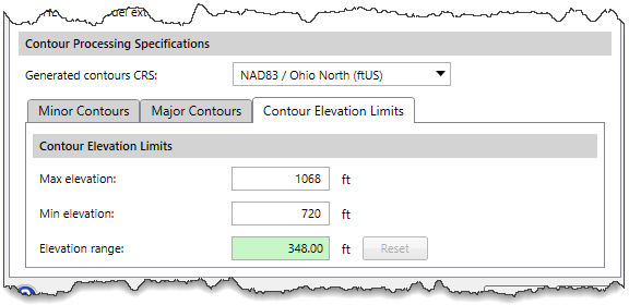
The Generated contours CRS dropdown combo box allows the user to select the Coordinate Reference System (CRS) that the generated contours will be created with. By default, the software selects the project’s CRS. Refer to this article in our knowledge base to learn more about coordinate reference systems.
This section allows the user to create minor contours by specifying layer name, interval, width, and color. The Minor Contours checkbox is enabled by default.
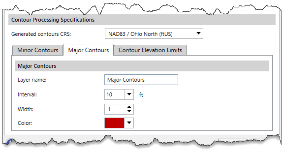
This section allows the user to create major contours by specifying layer name, interval, width, and color.
This section allows the user to define elevation limits for generating contours. For example, the user may not be interested in generating contours above the river valley in very steep terrain. This option limits the contours that are generated, thereby speeding up the process and making the size of the project file smaller.
After the contour options have been defined, click the [Generate] button and the software will generate the contours.
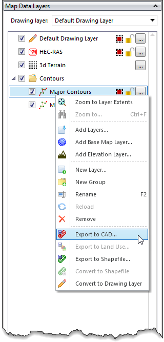
From the Map Data Layers panel, expand the Contours group to see the details of the generated contours. The user can also export the contours to AutoCAD or MicroStation by right-clicking on a contour layer and then selecting the Export to CAD command from the displayed context menu.


CivilGEO G2 Reviews
4.8/5.0 Rating, Over 230 Reviews

GeoHECRAS is recognized as the top Civil Engineering Design Software with an average of 4.8 out of 5.0 rating from over 230 real user reviews on G2.


We use cookies to give you the best online experience. By agreeing you accept the use of cookies in accordance with our cookie policy.
When you visit any web site, it may store or retrieve information on your browser, mostly in the form of cookies. Control your personal Cookie Services here.


