
Welcome to CivilGEO Knowledge Base
Welcome to CivilGEO Knowledge Base
The Extract Roadway Geometry command allows the user to extract high chord geometry and internal bridge geometry of roadway crossings from digital terrain layers. Additionally, for 2D roadway crossings, the user can extract the elevation data from approach and exit cross sections. The extracted geometry data will automatically get populated in the appropriate fields of the bridge and culvert data dialog boxes.
Note that 1D roadway crossing geometry data will get populated into the Bridge & Culvert Data dialog box, whereas 2D roadway crossing geometry data will get populated into the 2D Bridge & Culvert Data dialog box.
Refer to the below articles in our knowledge base to learn more about 1D and 2D bridge modeling:
Follow the steps below to use the Extract Roadway Geometry command:
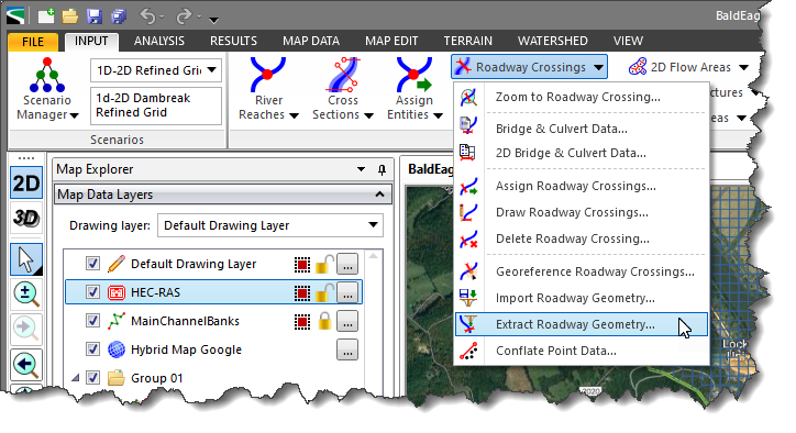
Note that this command is also available in the roadway crossing right-click context menu.
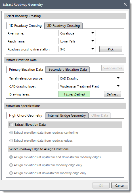
The following sections describe the Extract Roadway Geometry command and how to interact with the above dialog box.
The Select Roadway Crossing section allows the user to select the roadway crossing in order to extract the roadway geometry. It contains two panels:
The Extract Roadway Crossing dialog box will default to either the 1D or 2D Roadway Crossing panel based on the following criteria:
The 1D Roadway Crossing panel allows the user to select the river, corresponding reach, and the roadway crossing river station from the River name, Reach name, and Roadway crossing river station dropdown combo boxes. Alternatively, the user can click the [Pick] button to select the roadway crossing river station from the Map View.
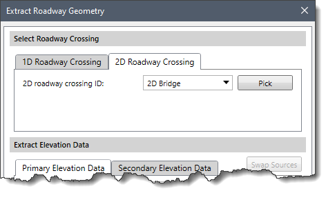
The 2D Roadway Crossing panel allows the user to select the 2D roadway crossing from the 2D roadway crossing ID dropdown combo box. Alternatively, the user can click the [Pick] button to select the 2D roadway crossing from the Map View.
This section is used to define the elevation data source(s) to be used to extract the roadway geometry.
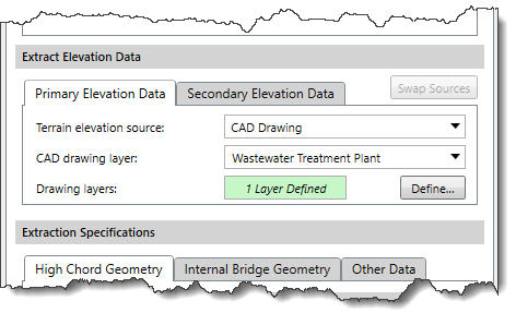
The user can use the Primary and Secondary Elevation Data panels to define the primary and secondary (if available in the project) elevation data sources for extracting the roadway geometry. Different options are provided to specify additional elevation data information depending on the selected elevation data source type.
The following elevation data formats are supported:
When a secondary elevation data source is available, the software will form a concave hull around the primary elevation data source to identify its bounds. For locations where elevation data from the primary data source is unavailable, the software will use the elevation data from the secondary data source.
Note that the user cannot utilize the same data source to define both the primary and secondary elevation data.
The user can click the [Swap Sources] button to swap the selected elevation source from primary elevation data to secondary elevation data and vice versa.
This section is used to define the specifications for extracting the roadway geometry. The user can extract the high chord geometry of the roadway crossing and the internal bridge geometry. For 2D models, the user can also extract the elevation data from approach and exit cross sections.
The following panels are provided in this section:
This panel is used to specify general parameters for extracting high chord roadway geometry. The extracted elevation at the roadway high chord vertices will get populated in the appropriate fields of the bridge and culvert data dialog boxes.
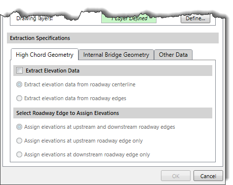
By default, the options in this panel are disabled (i.e., grayed out). The user can select the Extract Elevation Data checkbox to enable the content of this panel. If this checkbox is left unchecked, the software will not extract high chord roadway geometry.
The following options are provided to extract elevation data:
The following options are provided to assign elevations at roadway edges:
This panel is used to provide general specifications for extracting the bridge’s internal geometry. The extracted internal bridge geometry data will get populated in the appropriate fields of the bridge and culvert data dialog boxes.
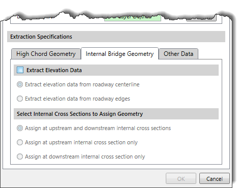
By default, the options in this panel are disabled (i.e., grayed out). The user can select the Extract Elevation Data checkbox to enable the content of this panel. If this checkbox is left unchecked, the software will not extract the internal bridge geometry.
Note that the options provided to extract the elevation data in this panel are similar to that of the High Chord Geometry panel.
The following options are provided to assign geometry to internal cross sections:
This panel is enabled only for 2D roadway crossings. It allows the user to extract elevation data from approach and exit cross sections.
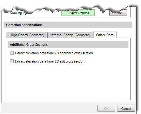
The following parameters are provided in the panel:
When all the data has been defined, the user can click the [OK] button to extract and populate the roadway geometry data into the appropriate fields of bridge and culvert data dialog boxes.


CivilGEO G2 Reviews
4.8/5.0 Rating, Over 230 Reviews

GeoHECRAS is recognized as the top Civil Engineering Design Software with an average of 4.8 out of 5.0 rating from over 230 real user reviews on G2.


We use cookies to give you the best online experience. By agreeing you accept the use of cookies in accordance with our cookie policy.
When you visit any web site, it may store or retrieve information on your browser, mostly in the form of cookies. Control your personal Cookie Services here.


