
Welcome to CivilGEO Knowledge Base
Welcome to CivilGEO Knowledge Base
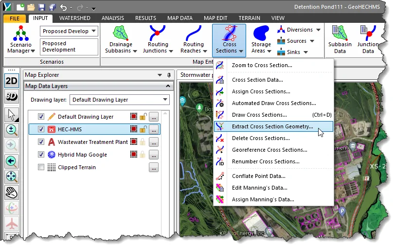
In GeoHECHMS, the Extract Cross Section Geometry command allows the user to extract the cross section geometry from an underlying elevation grid where valid elevation data are present. The software will automatically recognize the limits of the elevation data and extract the cross section geometry for that data. It will not try to extract cross section geometry data where valid elevation data are not present.
For example, the underlying elevation grid might be of the river channel only. Previously, extracting the cross section geometry for this area required that the user define the channel bank stations at the limits of the elevation data and then extract the cross section geometry only for the cross section channel. If the user tried to extract the cross section geometry for the overbank areas, the overbank geometry would be flat.
Follow the steps given below to use the Extract Cross Section Geometry command:
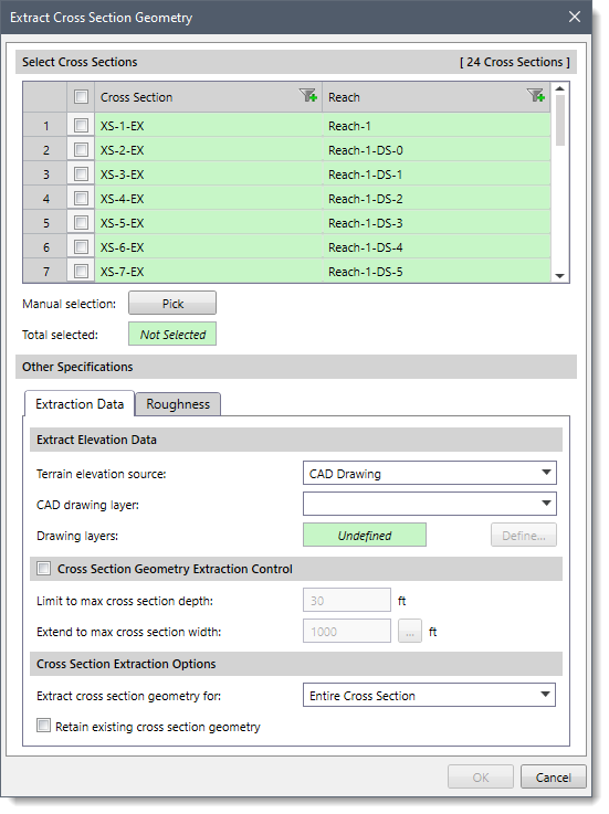
The following sections describe how to use the Extract Cross Section Geometry command and interact with the above dialog box.
The Select Cross Sections section is used to manually select cross sections in order to extract geometry. If a cross section is already selected on the Map View prior to running this command, the same cross section will be shown selected within the table.
Alternatively, the user can click the [Pick] button to interactively select the cross sections from the Map View. The dialog box will temporarily disappear. Either select cross sections one by one, or click on the reach and all associated cross sections will be selected from the Map View. After selecting the cross sections, press the [Enter] key or right-click and choose Done from the displayed context menu. The Extract Cross Section Geometry dialog box will be redisplayed and the total number of selected cross sections will be shown in the Total selected read-only field.
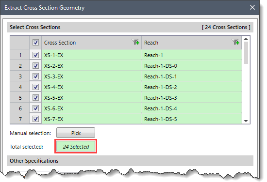
In addition, the user can select/deselect the desired cross section by checking/unchecking the checkboxes corresponding to each cross section in the table listing.
This panel is used to define the data extraction specifications for the selected cross sections.
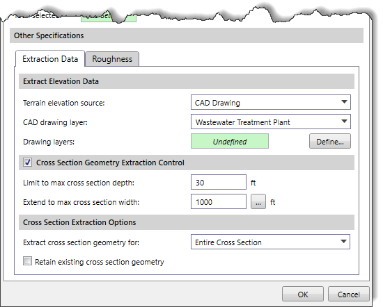
The Extract Elevation Data section is used to define the elevation data source(s) to be used for extracting the cross section geometry. Depending on the selected elevation data source type, the content of this panel changes to specify additional elevation data information.
Refer to this article in our knowledge base for information on the types of terrain elevation data that can be used for constructing cross sections.
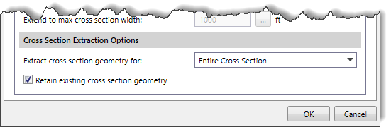
This optional section is used to provide additional control in terms of the cross section geometry data to be extracted from the terrain model for the selected cross section polylines. These controls provide additional intelligence on whether to extend or limit the cross section cutting, based upon whether specific criteria have been met. This assures the user that adequately deep cross sections have been created on both sides of the river reach. The software will attempt to retrieve the cross section geometry data to the depth specified within the specified maximum cross section width.
If the selected polylines do not extend outward far enough to get the cross section depth specified, the software will automatically extend the cross sections further outward. Similarly, if the selected polylines extend too far outward for the cross section depth specified, the software will automatically trim the cross sections.
By default, this section is disabled (i.e., grayed out). Select the Cross Section Geometry Extraction Control checkbox to enable this section.
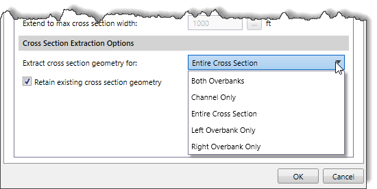
This section is used to control which portions of the cross section(s) are to be extracted.
For example, the user may have survey data for the cross section channel and a LIDAR digital terrain surface for the overbank areas.
In this example, the user would only want to extract the cross section geometry for the overbank areas since the surveyed channel geometry is already accurate.
The Extract cross section geometry for dropdown combo box entry contains the following options:
The Retain existing cross section geometry checkbox option is used to retain the geometry of the cross sections that were extracted previously using the CAD file. By default, this checkbox is unchecked.
During the extraction of the cross section geometry, the software will automatically assign a default Manning’s roughness for the left overbank, channel, and right overbank areas. However, the user can adjust these Manning’s roughness values in the Roughness panel as shown below.
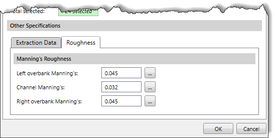
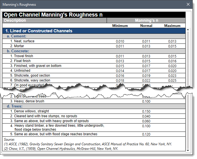
Note that, while defining the Manning’s n values, the user can click the […] button to display the Manning’s Roughness dialog box. This dialog box provides a reference to Manning’s roughness coefficients for some commonly used surface materials.
When all the options have been defined, click the [OK] button and the software will extract the cross section geometry from the elevation terrain.


CivilGEO G2 Reviews
4.8/5.0 Rating, Over 230 Reviews

GeoHECRAS is recognized as the top Civil Engineering Design Software with an average of 4.8 out of 5.0 rating from over 230 real user reviews on G2.


We use cookies to give you the best online experience. By agreeing you accept the use of cookies in accordance with our cookie policy.
When you visit any web site, it may store or retrieve information on your browser, mostly in the form of cookies. Control your personal Cookie Services here.


