
Welcome to CivilGEO Knowledge Base
Welcome to CivilGEO Knowledge Base
The Drawing Element Properties dialog box allows the user to define various elements and their properties on the drawing layer, style the border associated with the element, change the image’s transparency, change the current CRS (coordinate reference system) of the project and automatically apply the transformation scale factor on any particular layer to accurately map it to the project CRS.
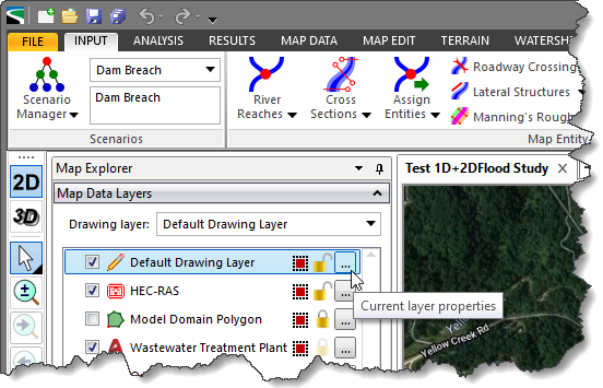
Follow the steps given below to open the Drawing Element Properties dialog box:
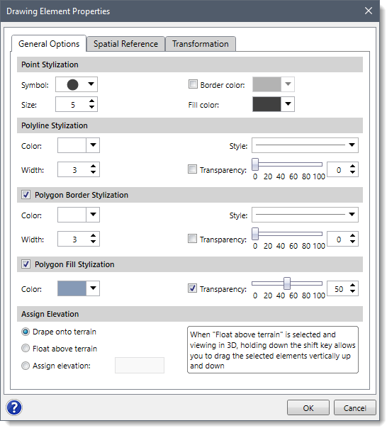
The Drawing Element Properties dialog box contains three tabs as described below:
Various sections of the General Options tab are described below:
The Spatial Reference tab allows the user to manually assign the project’s CRS to the non-CRS referenced data layer if the data layer coordinates lie within the project’s CRS. Refer to this article in our knowledge base to learn more about spatial reference.
The Transformation tab allows the user to automatically apply the transformation scale factor to any particular layer and accurately map it to the project coordinate reference system (CRS). Refer to this article in our knowledge base to learn more about layer transformation.


CivilGEO G2 Reviews
4.8/5.0 Rating, Over 230 Reviews

GeoHECRAS is recognized as the top Civil Engineering Design Software with an average of 4.8 out of 5.0 rating from over 230 real user reviews on G2.


We use cookies to give you the best online experience. By agreeing you accept the use of cookies in accordance with our cookie policy.
When you visit any web site, it may store or retrieve information on your browser, mostly in the form of cookies. Control your personal Cookie Services here.


