
Welcome to CivilGEO Knowledge Base
Welcome to CivilGEO Knowledge Base
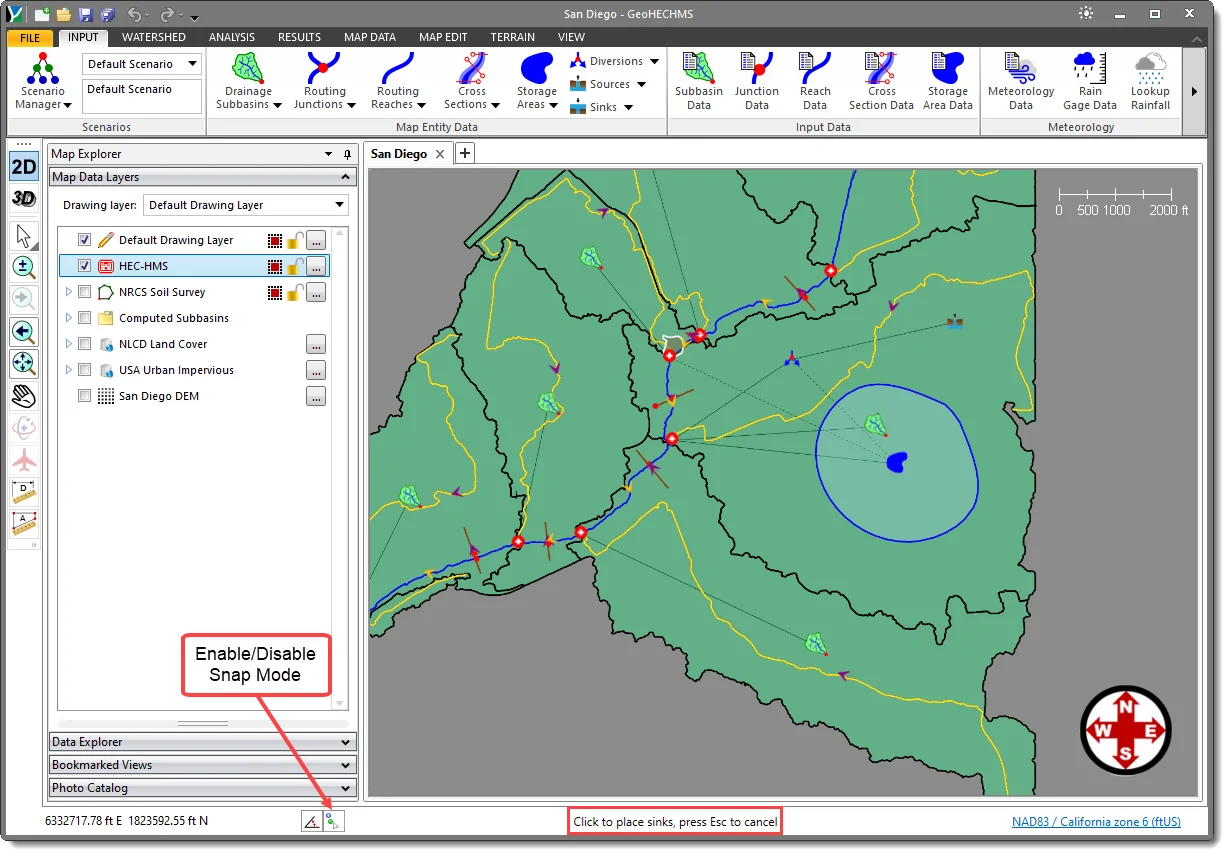
Sinks define the elements (i.e., dry wells, wet wells, etc.) where one or more inflows enter, but there are no outflows. Multiple inflows in a sink element are added to determine the total amount of water entering the element. Sinks can be used to represent the lowest point of an interior drainage area or the outlet of the basin model.
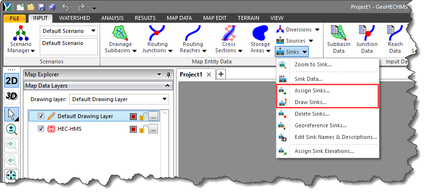
In GeoHECHMS, sinks can be defined by either drawing or assigning nodes on the Map View using the following commands:
The Draw/Assign Sinks command is used to manually draw/assign multiple sink nodes on the Map View, one after another until completed.
Follow the steps below to use the Draw/Assign Sinks command:
The following sections describe how to use the Draw/Assign Sinks command and interact with the above dialog box(s).
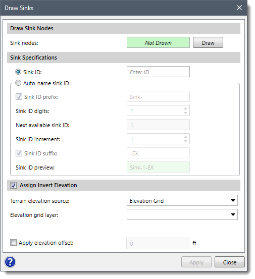
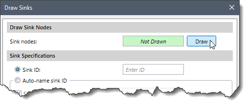
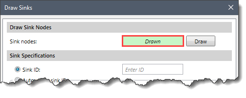
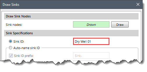
The Draw Sink Nodes section is used to draw sinks on the Map View using nodes. To draw sink nodes, follow the steps below:
 Notes:
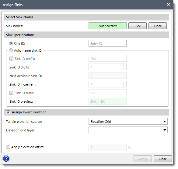
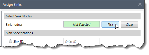
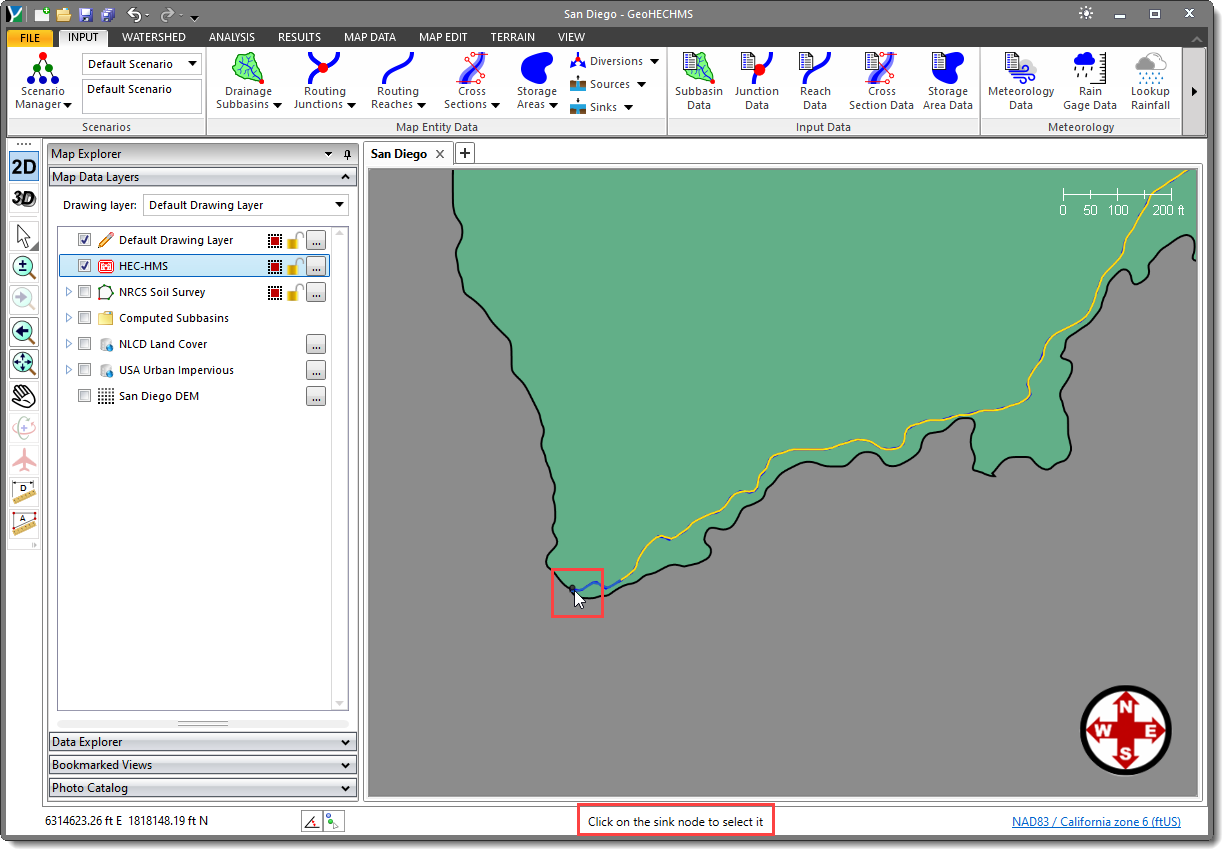
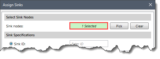
The Select Sink Nodes section can be used to manually assign multiple nodes on the Map View as sinks. To assign sink nodes, follow the steps below:
This section is common to both the Draw Sinks and Assign Sinks dialog box and is used to specify the sink ID for each drawn/assigned sink. The user can assign these IDs either manually or automatically using some predefined formats.
Follow the steps below to assign sink IDs to the sinks:
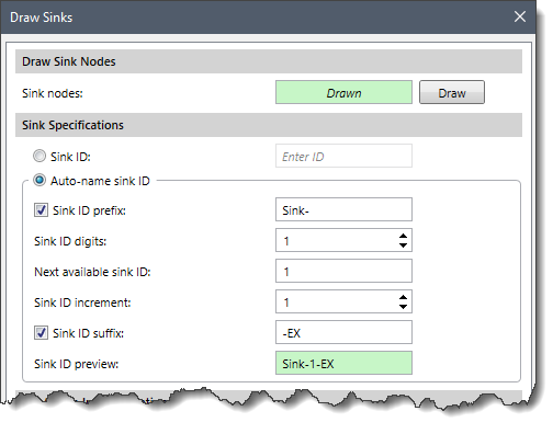 The different naming formats present in the Auto-name sink ID option are as follows:
Note that if the auto-name option is enabled and the user returns to the dialog box, the [Apply] button will be disabled since the just drawn/assigned sinks have already been named and created.
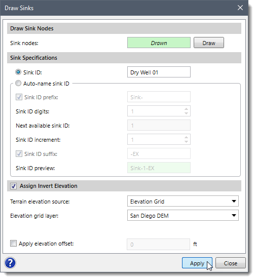
This section is common to both the Draw Sinks and Assign Sinks dialog box and allows the user to assign an invert elevation to the sink using a terrain model. Define this section before drawing/assigning sinks so that invert elevations can be assigned.
To assign an invert elevation, the Terrain elevation source dropdown combo box supports the following surface types:
The user can also apply an elevation offset to raise or lower the sink by the specified amount by checking the Apply elevation offset checkbox. On selecting this checkbox, the entry field next to it becomes available for entering an elevation offset value. A negative offset value will lower the sink by the specified amount.


CivilGEO G2 Reviews
4.8/5.0 Rating, Over 230 Reviews

GeoHECRAS is recognized as the top Civil Engineering Design Software with an average of 4.8 out of 5.0 rating from over 230 real user reviews on G2.


We use cookies to give you the best online experience. By agreeing you accept the use of cookies in accordance with our cookie policy.
When you visit any web site, it may store or retrieve information on your browser, mostly in the form of cookies. Control your personal Cookie Services here.


