Boundary condition lines are defined to represent different flow conditions or constraints for 2D flow areas or storage areas. Boundary conditions consist of external boundary conditions along the perimeter of the 2D area and internal boundary conditions. Internal boundary conditions are used to attach a Flow Hydrograph inside of the computational domain. External boundary conditions are used for a Flow Hydrograph, Stage Hydrograph, Rating Curve, and Normal Depth. When creating a boundary condition line, the line outside of the storage area or 2D flow area will be considered as an external boundary. Otherwise, it will be treated as an internal boundary.
In GeoHECRAS, the user can define boundary condition lines just outside or entirely inside a 2D flow area and storage area. This is accomplished by drawing or assigning the polyline(s) on the Map View using the following commands:
- Draw SA/2D Boundary Condition Lines
- Assign SA/2D Boundary Condition Lines
After drawing or assigning the boundary condition lines along the storage areas or 2D flow areas, the user can define the boundary condition types/data for each of these boundary condition lines using the Unsteady Flow Data command. Refer to this article in our knowledge base to learn more about how to define the boundary condition types and data.
Drawing SA/2D Boundary Condition Lines
The Draw SA/2D Boundary Condition Lines command allows the user to manually draw storage area or 2D flow area boundary condition lines on the Map View.
Follow the steps below to draw the SA/2D boundary condition lines:
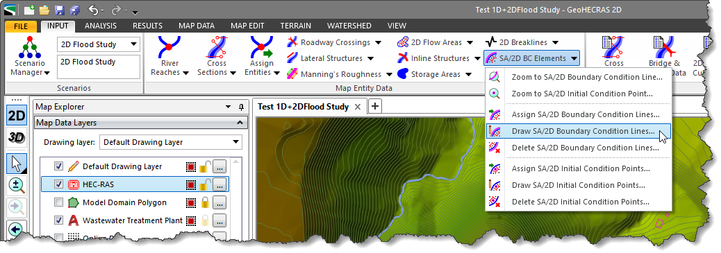
- From the Input ribbon menu, select the SA/2D BC Elements menu item, and then choose the Draw SA/2D Boundary Condition Lines command.
- The Draw SA/2D Boundary Condition Lines dialog box will be displayed.
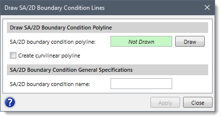
- Click the [Draw] button adjacent to the SA/2D boundary condition polyline field. Use the Create curvilinear polyline checkbox option to draw the polyline using curvilinear segments.
- The Draw SA/2D Boundary Condition Lines dialog box will temporarily disappear, and a prompt will be displayed on the status bar directing the user on what to do next.
- Draw the boundary condition polyline just outside or entirely inside a 2D flow area/storage area from left to right looking downstream direction on the Map View. While drawing elements, the user can use the [Ctrl] key to switch between the curvilinear and the linear digitizing. Refer to this article in our knowledge base to learn more about drawing elements on the Map View. When finished, press the [Enter] key or right-click and select Done from the displayed context menu.
- The Draw SA/2D Boundary Condition Lines dialog box will be redisplayed and the status of the SA/2D boundary condition polyline read-only field will be changed from Not Drawn to Drawn.
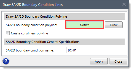
- The software automatically names the drawn storage area or 2D flow area boundary condition line in the SA/2D Boundary Condition General Specification section. Note that the user can also change the name to whatever is desired in the SA/2D boundary condition name entry field.
- Click the [Apply] button and the SA/2D boundary condition line will be created.
Assigning SA/2D Boundary Condition Lines
The Assign SA/2D Boundary Condition Lines command allows the user to manually assign individual polyline(s) as a storage area or 2D flow area boundary condition line. To use this command, a polyline that can be selected for the purpose of assigning the SA/2D boundary condition line must already exist on the Map View.
Follow the steps below to assign the SA/2D boundary condition lines:
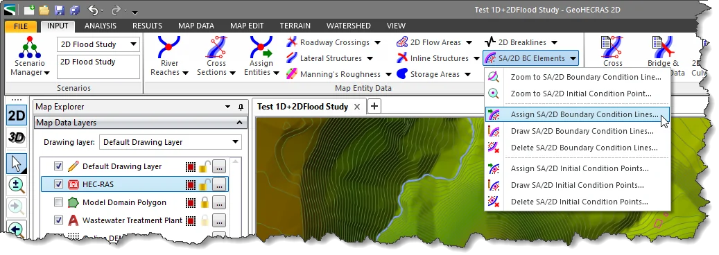
- From the Input ribbon menu, select the SA/2D BC Elements menu item, and then choose the Assign SA/2D Boundary Condition Lines command.
- The Assign SA/2D Boundary Condition Lines dialog box will be displayed.
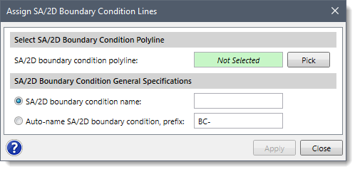
- Click the [Pick] button adjacent to the SA/2D boundary condition polyline field.
- The Assign SA/2D Boundary Condition Lines dialog box will temporarily disappear, and a prompt will be displayed on the status bar directing the user what to do next.
- From the Map View, click on the boundary condition polyline(s) along the edge or interior of the storage area or 2D flow area to select them. When finished, press the [Enter] key or right-click and select Done from the displayed context menu.
- The Assign SA/2D Boundary Condition Lines dialog box will be redisplayed, and the number of selected polylines will be shown in the SA/2D boundary condition polyline entry, as shown below.
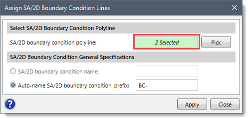
- In the SA/2D Boundary Condition General Specifications section, define the prefix for the names of the SA/2D boundary condition lines in the Auto-name SA/2D boundary condition, prefix entry field.
Note that the SA/2D boundary condition name option is only available when a single polyline is selected. The user can then define the name of the storage area or 2D flow area boundary condition lines in the SA/2D boundary condition name entry field. Otherwise, the software auto-names the SA/2D boundary condition lines using the defined prefix, for example BC-##, where ## represents the boundary condition lines count (i.e., 01, 02, and so on) and BC represents the prefix.
- Click the [Apply] button, and the software will treat the selected polyline(s) as SA/2D boundary condition line(s).


