
Welcome to CivilGEO Knowledge Base
Welcome to CivilGEO Knowledge Base
River junctions are defined as locations where two or more river reaches join together or split apart.
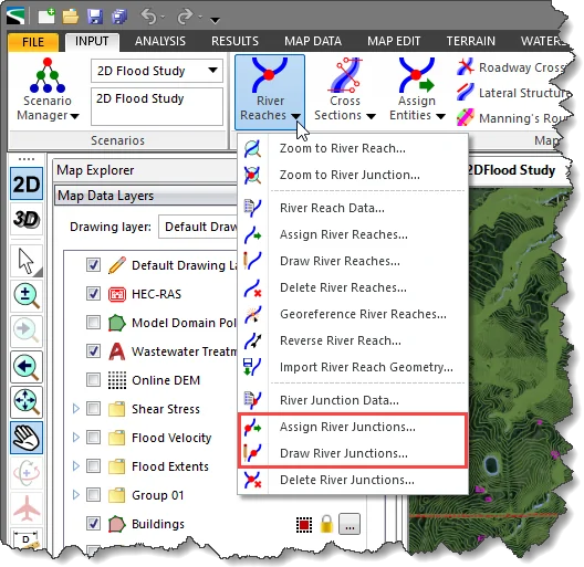
In GeoHECRAS, river junctions can be defined by either drawing or assigning nodes on the Map View using the following commands:
The Draw/Assign River Junctions command allows the user to manually draw/assign multiple nodes on the Map View as river junctions, one after another until completed.
Follow the steps below to use the Draw/Assign River Junctions command:
The following sections describe how to use the Draw and Assign River Junctions command and interact with the above dialog boxes.
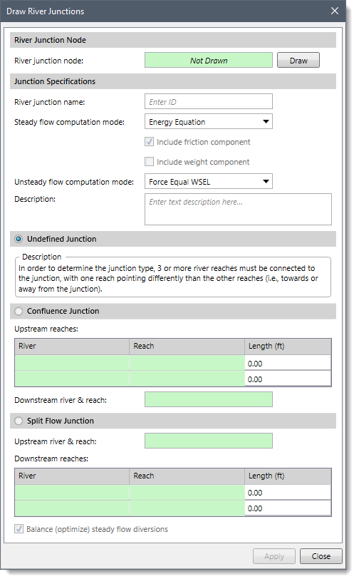
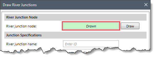
The River Junction Node section is used to manually draw nodes on the Map View as river junctions. The user can draw the river junctions either before or after the river reaches have been created. However, it is generally better to place the river junctions first, and then connect the river reaches to the junctions.
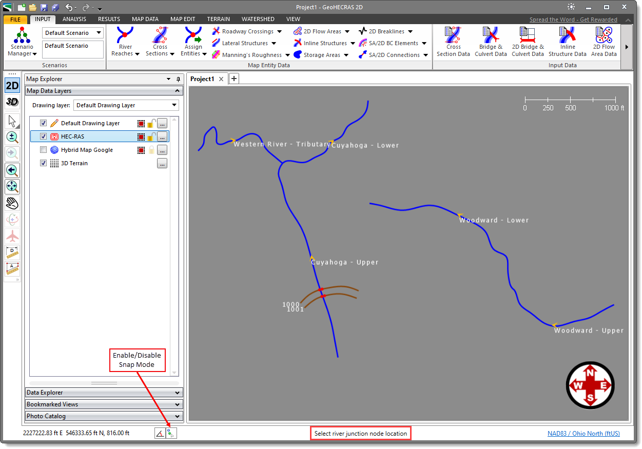
To draw a river junction node, follow the steps below:
![[Draw] button](/wp-content/uploads/sites/25/2023/05/Draw-and-Assign-River-Junctions-Command-Image-4.png)
 Notes:
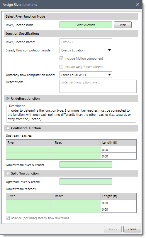
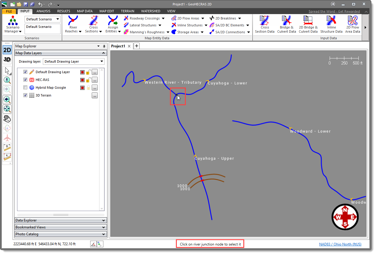
The Select River Junction Node section can be used to manually assign previously drawn nodes on the Map View as river junctions. Note that at least three river reaches must be connected to the node to be assigned as river junctions.
To select river junction nodes, follow the steps below:
![[Pick] button](/wp-content/uploads/sites/25/2023/05/Draw-and-Assign-River-Junctions-Command-Image-7.png)
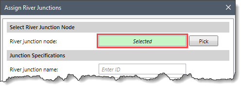
Note that if a river junction node has been preselected before running this command, the River junction node read-only field will be shown selected on opening the Assign River Junctions command.
This section is common to both the Draw River Junctions and Assign River Junctions dialog boxes and is used to specify the data for each drawn/assigned river junction.
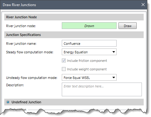
The following data are provided in this section:
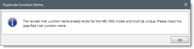 To abort the rename operation, press the [Esc] key.
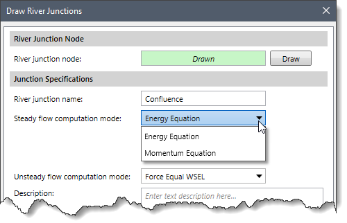 To learn more about the methods available in the dropdown combo box, refer to this article in our knowledge base.
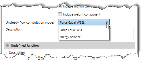 To learn more about the methods available in the dropdown combo box, refer to this article in our knowledge base.
The dialog box automatically defines the types of river junctions of the selected node. The software automatically determines the type of junction based upon the number of river reaches that are connected to the node, as well as the direction of the river reaches. The user cannot override the selected junction type radio button option.
The following types of junctions are available in the dialog box:
This radio button selection section defines the junction as undefined when the following conditions have not been met:
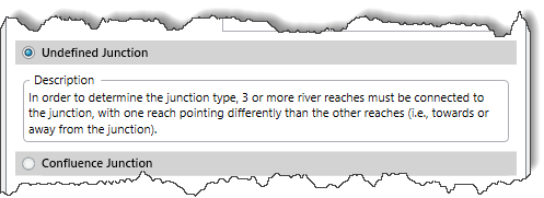
This radio button selection section defines data for river confluences, where rivers combine flow into a single reach. This junction type requires the following conditions to be met:
The following data correspond to this radio button selection section.
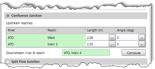
To learn more about this section, refer to this article in our knowledge base.
This radio button selection section is used to define data for split flow diversions, where a river splits into two (or more) river reaches. This junction type requires the following conditions to be met:
The following data corresponds to this radio button selection section:
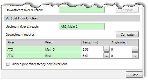
To learn more about this section, refer to this article in our knowledge base.


CivilGEO G2 Reviews
4.8/5.0 Rating, Over 230 Reviews

GeoHECRAS is recognized as the top Civil Engineering Design Software with an average of 4.8 out of 5.0 rating from over 230 real user reviews on G2.


We use cookies to give you the best online experience. By agreeing you accept the use of cookies in accordance with our cookie policy.
When you visit any web site, it may store or retrieve information on your browser, mostly in the form of cookies. Control your personal Cookie Services here.


