
Welcome to CivilGEO Knowledge Base
Welcome to CivilGEO Knowledge Base
Junction elements are used to combine runoff and stream flow from hydrologic elements located upstream. The inflow into the junction element can come from one or multiple upstream elements.
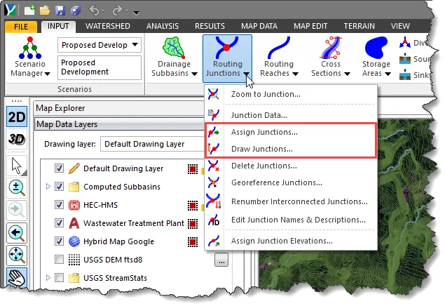
In GeoHECHMS, junctions can be defined by either drawing or assigning nodes on the Map View using the following commands:
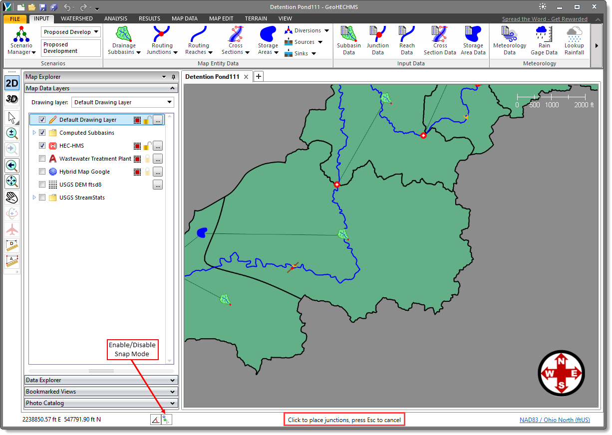
The Draw/Assign Junctions command allows the user to manually draw/assign multiple nodes on the Map View as junctions, one after another until completed.
Follow the steps below to use the Draw/Assign Junctions command:
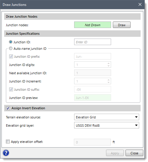
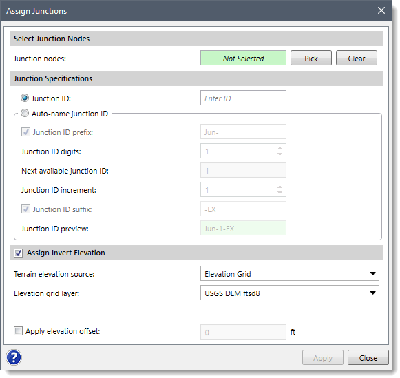
The following sections describe how to use the Draw/Assign Junctions command and interact with the above dialog box(s).
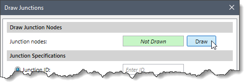
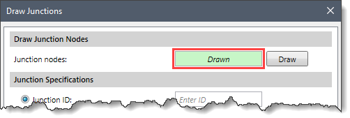
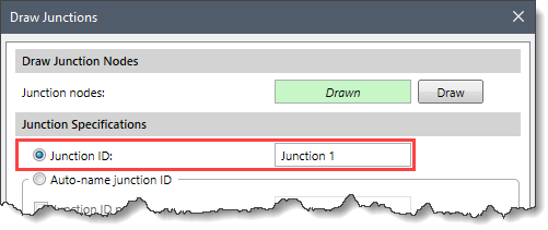
The Draw Junction Nodes section is used to place/draw the junction on the Map View using nodes. To draw a junction node, follow the steps below:
 Notes:
 To abort the current draw command, press the [Esc] key.
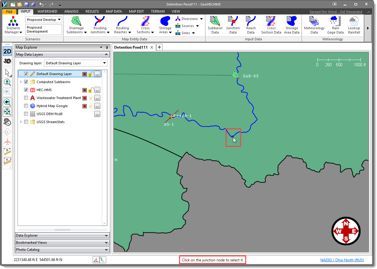
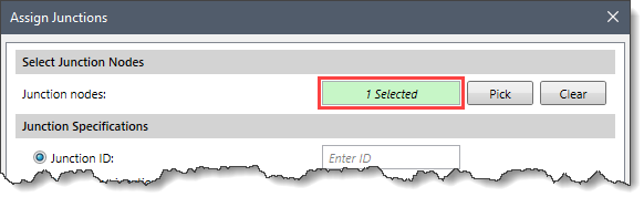
The Select Junction Nodes section can be used to manually assign multiple nodes on the Map View as junctions. To assign junction nodes, follow the steps below:
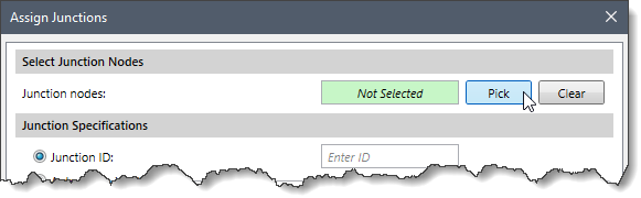
This section is common to both the Draw Junctions and Assign Junctions dialog box and is used to specify the junction ID for each drawn/assigned junction. The user can assign these IDs either manually or automatically using some predefined formats.
Follow the steps below to assign junction IDs to the junctions:
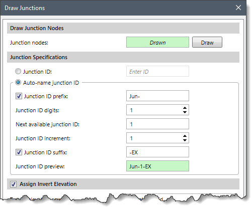
The different junction naming formats present in the Auto-name junction ID option are as follows:
![[Apply] button](/wp-content/uploads/sites/25/2021/05/Draw-and-Assign-Junctions-Command-Img-12.png) Note that if the auto-name option was selected and the user returns to the dialog box, the [Apply] button is disabled since the just drawn/assigned junctions have already been named and created.
Note that if the auto-name option was selected and the user returns to the dialog box, the [Apply] button is disabled since the just drawn/assigned junctions have already been named and created.This section is common to both the Draw Junctions and Assign Junctions dialog box and allows the user to assign an invert elevation to the junction using a terrain model. Define this section before drawing/assigning junctions so that invert elevations can be assigned.
To assign an invert elevation, the Terrain elevation source dropdown combo box supports the following surface types:
The user can also apply an elevation offset to raise or lower the junction by the specified amount by checking the Apply elevation offset checkbox option. On selecting this checkbox option, the entry field next to it becomes available for entering an elevation offset value. A negative offset value will lower the junction by the specified amount.


CivilGEO G2 Reviews
4.8/5.0 Rating, Over 230 Reviews

GeoHECRAS is recognized as the top Civil Engineering Design Software with an average of 4.8 out of 5.0 rating from over 230 real user reviews on G2.


We use cookies to give you the best online experience. By agreeing you accept the use of cookies in accordance with our cookie policy.
When you visit any web site, it may store or retrieve information on your browser, mostly in the form of cookies. Control your personal Cookie Services here.


