
Welcome to CivilGEO Knowledge Base
Welcome to CivilGEO Knowledge Base
GeoHECHMS allows the user to draw or assign a polyline for each subbasin to function as the overland flow path for computing the SCS TR-55 Time of Concentration / Lag Time.
Lag Time and Time of Concentration (TOC) are two different but related terms that are used in hydrology computations. They represent the time required for runoff to travel from the hydraulically most distant point in the watershed to the outlet. The hydraulically most distant point is the point with the longest travel time to the watershed outlet, but it is not necessarily the point with the longest flow distance to the outlet. It is a function of the topography, hydrologic soil type, and land use within the subbasin. There are many different methods for computing Lag Time and Time of Concentration, but generally the computations are dependent upon slope and character of the subbasin and flow path.
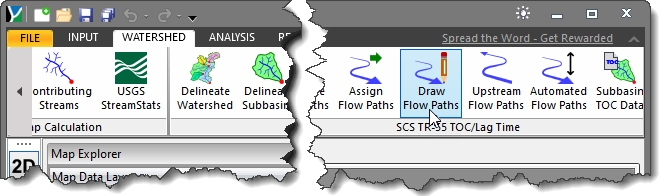
The Draw Flow Paths command allows the user to draw a polyline on the Map View to be used as a subbasin flow path line for computing the TOC / Lag Time.
Follow the steps below to use the Draw Flow Paths command:
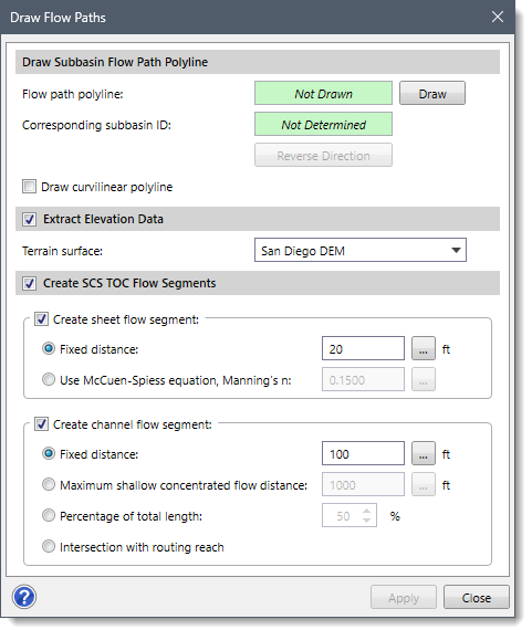
The following sections describe how to interact with the above dialog box.
The Flow path polyline entry specifies whether a flow path line has been drawn. Clicking the [Draw] button causes the dialog box to disappear, at which point the user is then prompted to draw a corresponding subbasin flow path line for computing the TOC.
After drawing the flow path line, the user is immediately returned to the dialog box. The software then determines which subbasin the flow path line corresponds to and displays the subbasin ID in the dialog box.
The user can turn on the Draw curvilinear polyline check box to add the curvilinear segments or can press the [Ctrl] key to enable the straight segments while drawing flow paths.
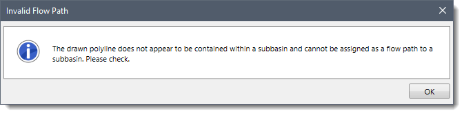
Note that the Draw Flow Paths command will check whether the drawn polyline is at least 90% contained within a subbasin polygon. If not, then the following informational message is displayed.
The Extract Elevation Data optional section is used to extract elevation from the defined terrain surface.
This option is enabled by default but recalls the user selection at the project level (when the file is saved).
The Create SCS TOC Flow Segments optional section is used to subdivide the assigned flow path into flow segments for assigning SCS TOC. It is enabled by default but recalls the user selection at the project level (when the file is saved).
Note that the flow path default flow type is shallow concentrated flow.
Once all the data has been defined in the Draw Flow Paths dialog box, click the [Apply] button. The software will then create a corresponding subbasin flow path line for computing the TOC / Lag Time.
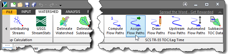
The Assign Flow Paths command allows the user to assign a polyline as subbasin flow path line for computing the TOC / Lag Time.
Follow the steps below to use the Assign Flow Paths command:
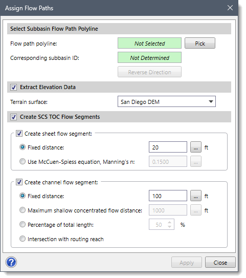
The following sections describe how to interact with the above dialog box.
The Flow path polyline entry specifies whether a flow path line has been selected. Clicking the [Pick] button causes the dialog box to disappear, at which point the user is then prompted to select a corresponding subbasin flow path line for computing the TOC.
After selecting the flow path line, the user is immediately returned to the dialog box. The software then determines which subbasin the flow path line corresponds to and displays the subbasin ID in the dialog box.
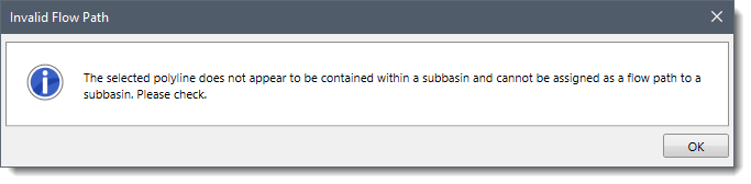
Note that the Assign Flow Path command will check whether the drawn polyline is at least 90% contained within a subbasin polygon. If more than 10% of the line resides outside of the subbasin, the following informational dialog box is displayed, and the selected polyline is not assigned as a flow path polyline.
 Note that the Extract Elevation Data and Create SCS TOC Flow Segments sections of the Assign Flow Paths command are similar to the Draw Flow Paths command, both of which have been explained in the previous sections of this article.
Once all the data has been defined in the Assign Flow Paths dialog box, click the [Apply] button. The software will then assign the selected polyline as a corresponding subbasin flow path line for computing the TOC / Lag Time.


CivilGEO G2 Reviews
4.8/5.0 Rating, Over 230 Reviews

GeoHECRAS is recognized as the top Civil Engineering Design Software with an average of 4.8 out of 5.0 rating from over 230 real user reviews on G2.


We use cookies to give you the best online experience. By agreeing you accept the use of cookies in accordance with our cookie policy.
When you visit any web site, it may store or retrieve information on your browser, mostly in the form of cookies. Control your personal Cookie Services here.


