
Welcome to CivilGEO Knowledge Base
Welcome to CivilGEO Knowledge Base
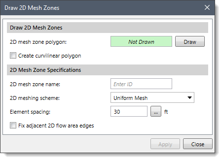
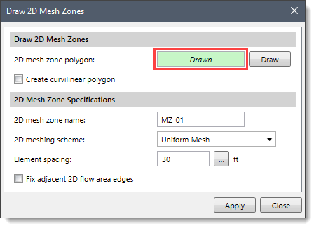
GeoHECRAS allows the user to assign or draw a 2D Mesh Zone polygon boundary and define the meshing scheme and corresponding parameters (e.g., element size, etc.). This allows the user to refine the mesh more easily in areas of interest and maintain that refinement as the model continues to be developed. For example, in a critical infrastructure area, a mesh zone could be created and defined, and a much smaller element size can be used to capture the flow direction and velocities that occur during a flood event.
In order to define a 2D Mesh Zone, a polygon is created to define the boundary of the mesh zone and a cell spacing system is provided to be used in the 2D Mesh Zone generation routine. 2D Mesh Zones can be used to densify an area where more detailed results are desired due to rapid changes in terrain or water surface elevation. Additionally, the 2D Mesh Zones allow the user to simplify an area where the water surface elevation will not change significantly, and users want to reduce the number of computation points in the 2D flow area.
To create 2D Mesh Zones, the Draw 2D Mesh Zones or Assign 2D Mesh Zones command can be used. Both commands work similarly.
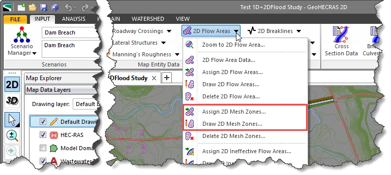
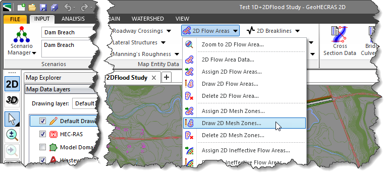
The Draw 2D Mesh Zones command allows the user to manually draw individual polygons on the Map View as 2D Mesh Zones.
Follow the steps below to use the Draw 2D Mesh Zones command:
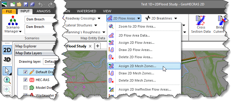
The Assign 2D Mesh Zones command allows the user to manually assign individual polygons as 2D Mesh Zones. To use this command, a polygon that can be selected must already exist on the Map View or a polygon shapefile layer must be loaded to represent mesh zones.
Follow the steps below to use the Assign 2D Mesh Zones command:
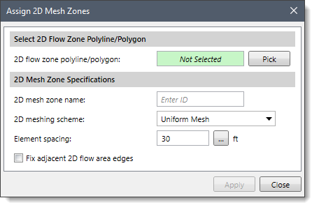
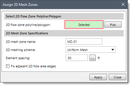 Note that the 2D Mesh Zone Specifications section of the Assign 2D Mesh Zones command is similar to that of the Draw 2D Mesh Zones command. Hence, refer to the Draw 2D Mesh Zones command section of this article to learn about the options available in this section.


CivilGEO G2 Reviews
4.8/5.0 Rating, Over 230 Reviews

GeoHECRAS is recognized as the top Civil Engineering Design Software with an average of 4.8 out of 5.0 rating from over 230 real user reviews on G2.


We use cookies to give you the best online experience. By agreeing you accept the use of cookies in accordance with our cookie policy.
When you visit any web site, it may store or retrieve information on your browser, mostly in the form of cookies. Control your personal Cookie Services here.


