
Welcome to CivilGEO Knowledge Base
Welcome to CivilGEO Knowledge Base
In GeoHECHMS, the Delineate Subbasins command delineates upstream drainage subbasins from user-selected locations, detailing the subbasin boundaries and upstream drainage tributaries that contribute runoff to the selected locations. If the selected locations are not on an existing stream, the locations are automatically “snapped” to the nearest stream, and then the corresponding subbasin is delineated.
Note that this command is similar to the Delineate Watershed command of the Watershed ribbon menu. These commands are different, however, in that the Delineate Subbasins command uses the user’s local elevation terrain surface while the Delineate Watershed command relies on the USGS WMS (Web Map Service) service and NED (National Elevation Data). To learn more about the Delineate Watershed command, refer to this article in our knowledge base.
To use the Delineate Subbasins command, follow the steps below:

The Delineate Subbasins command operates in three stages, as illustrated below. At each stage, the Delineate Subbasins dialog box provides the user with different options.
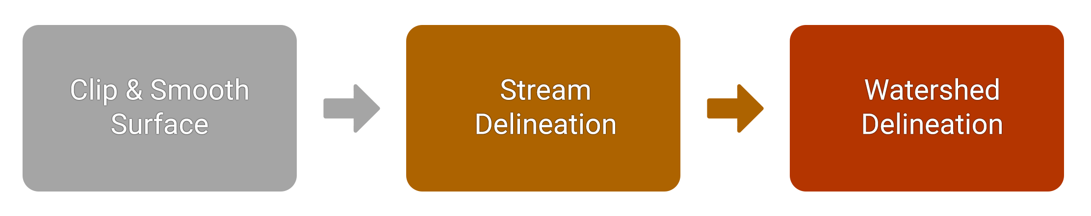
The below sections explain the above three stages and describe how to interact with the Delineate Subbasins dialog box.
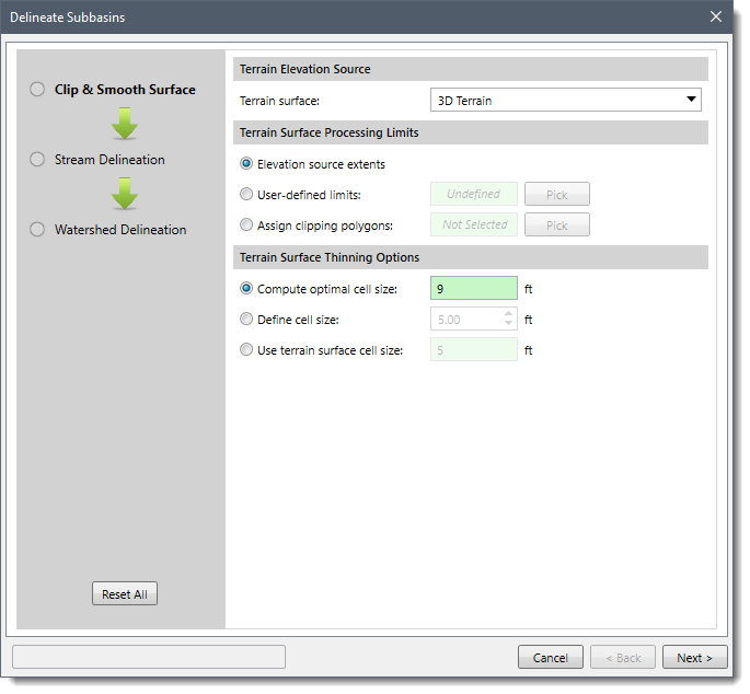
At this stage, the software performs clipping, thinning, and smoothing of the terrain surface. The following Delineate Subbasins dialog box will be displayed at this stage.
 In the above dialog box, the user needs to specify the following:
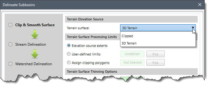
This section allows the user to select the elevation terrain surface. The Terrain surface dropdown combo box lists all the terrain surfaces that are already added to the project.
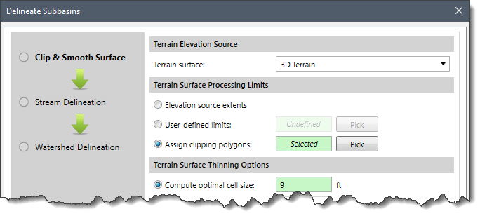
This section allows the user to define the area extent of the terrain surface that will be used to process terrain data.
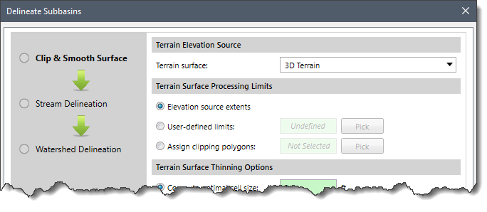 The user can select from three available options, as described below:
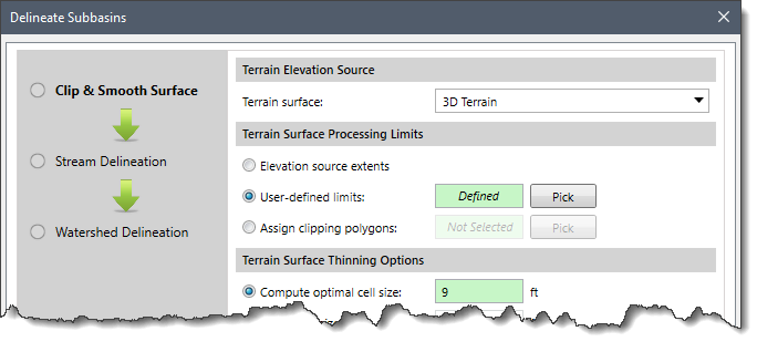
This section allows the user to define the cell size that will be used for thinning the terrain surface. The smaller the cell size value, the longer the processing time.
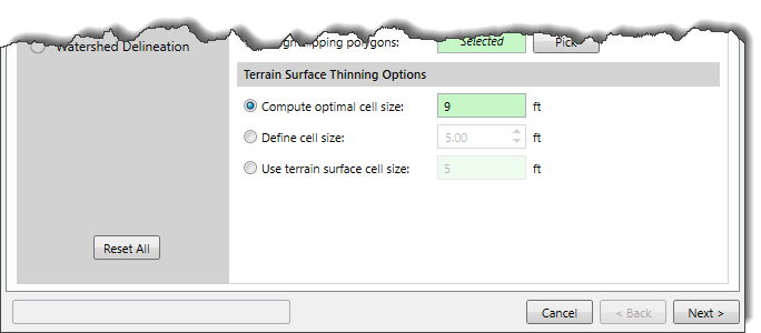 The user can select from three available options to define the cell size, as described below:
Once all the options in the Delineate Subbasins dialog box are configured, click the [Next] button. The processing of the Clip and Smooth Surface stage will begin. On completion, the control will automatically pass to the Stream Delineation stage.
At this stage, the software analyzes possible pits, filters, and extracts dissolved pits, as well as locates possible trenches, and performs stream network delineation. The following Delineate Subbasins dialog box will be displayed at this stage.
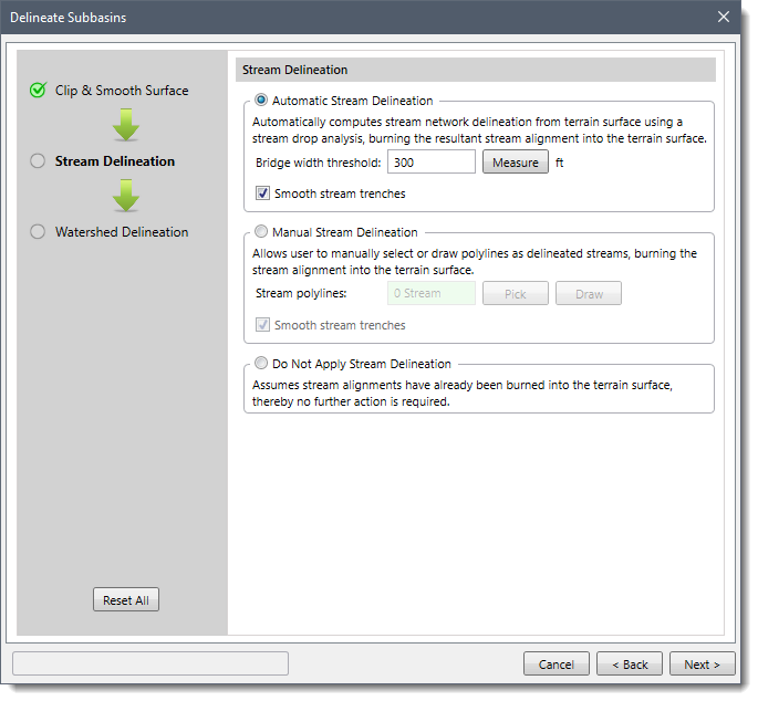 The software provides three options to choose from to perform stream delineation, as described below:
Selecting this option causes the software to automatically perform stream delineation using stream drop analysis.
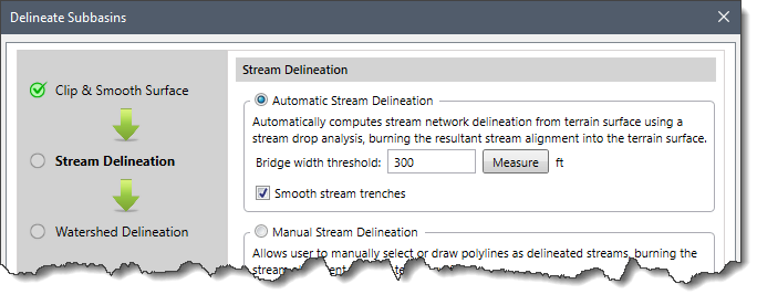 The Bridge width threshold input field allows the user to define the threshold value for the width of geographic obstructions such as roadways, bridges, and culverts that are burned on the terrain surface. These obstructions can affect the surface flow and break stream networks. Using the threshold value, the software can detect these obstructions and maintain the correct stream network. The user can enter the threshold value manually in the Bridge width threshold input field or click the [Measure] button to measure the threshold value of geographic obstructions from the Map View.
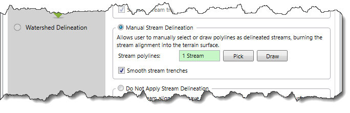
Selecting this option allows the user to manually select or draw polylines as delineated streams.
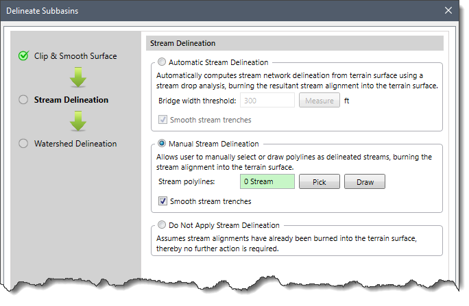
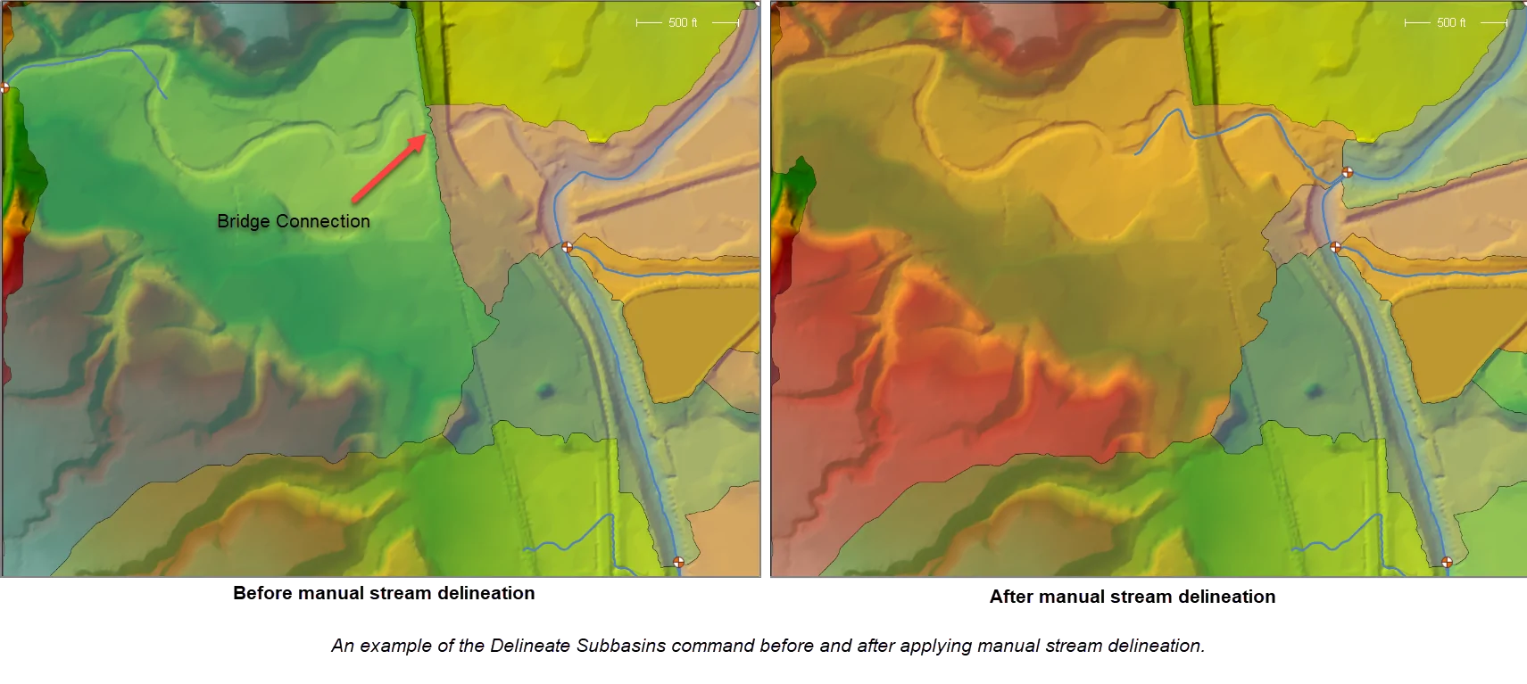
The Manual Stream Delineation option is useful when the user wants the delineation process to be more precise. For example, the user can quickly “burn-in” streams along bridge or culvert connections where one is missing. The software will honor the manually drawn stream alignment and force the delineation to follow that culvert or bridge connection to show the actual water flow.
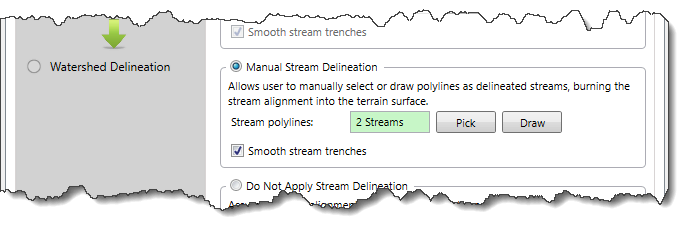
To assign already drawn polylines as delineated streams, follow the steps below:
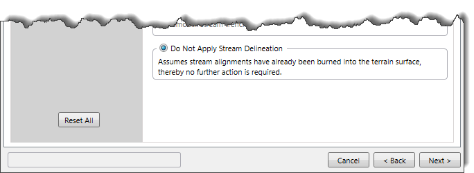
Selecting this option allows the user to skip the Stream Delineation stage. Select this option when the relevant elevation terrain surface already has a stream network burned on it.
Once all the options in the Delineate Subbasins dialog box are configured, click the [Next] button. The Stream Delineation process will begin. On completion, the software will automatically proceed to the Watershed Delineation stage.
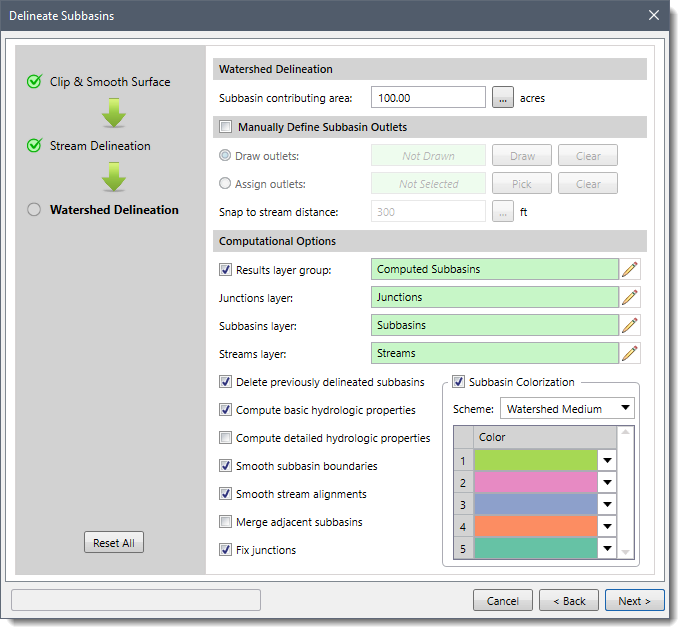
This is the last stage of the delineation process. At this stage, the software performs multiple tasks such as forming stream network and drainage subbasins, smoothing subbasin boundaries, and computing subbasin hydrology. The following Delineate Subbasins dialog box will be displayed at this stage.
 In the above dialog box, the user needs to specify the following:
This section allows the user to define the extent of the drainage accumulation area. This is the area that must be amassed for runoff to be considered as streamflow. Smaller values result in minor and major streams; larger values result in only major streams. By default, the software uses a value of 100 acres. The user can enter a different value for drainage accumulation area in the Subbasin contributing area input field or click the […] button to interactively measure it from the Map View.
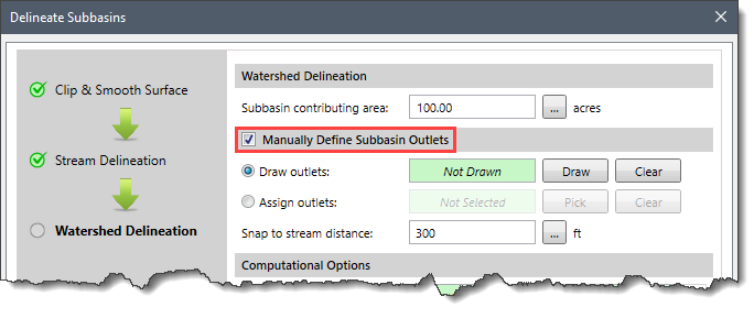
This section allows the user to manually draw outlets or select the already drawn outlets from the Map View. Select the Manually Define Subbasin Outlets checkbox to enable this section.
 Note that it is recommended to use the default settings. For example, if you specify the minimum subbasin area (Subbasin contributing area) to be too large and manually define the outlets, the smaller subbasins may not appear. The software discards the subbasins with smaller areas than the defined minimum subbasin area. As a result, rather than specifying large values for the minimum subbasin area, it is advisable to use the Merge adjacent subbasins option from the Computational Option section. If the subbasins still don’t show up, it is better to go with the default settings and let the software automatically find the placement of subbasins.
To draw the outlets on the Map View, follow the steps below:
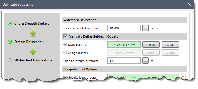
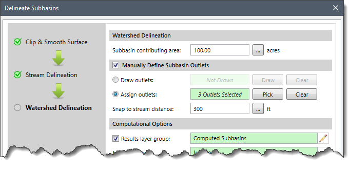
The user can define a threshold value for maximum distance to traverse for snapping the outlet point to the nearest stream in the Snap to stream distance input field. Alternatively, the user can click the […] button to measure the threshold value from the Map View. By default, the software uses a value of 300 ft.
This section provides multiple options to affect the subbasin’s appearance and delineation process.
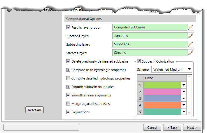 The following options are provided under the Computational Options section:
Once all the options in the Delineate Subbasins dialog box are configured, click the [Next] button. The Watershed Delineation process will begin.
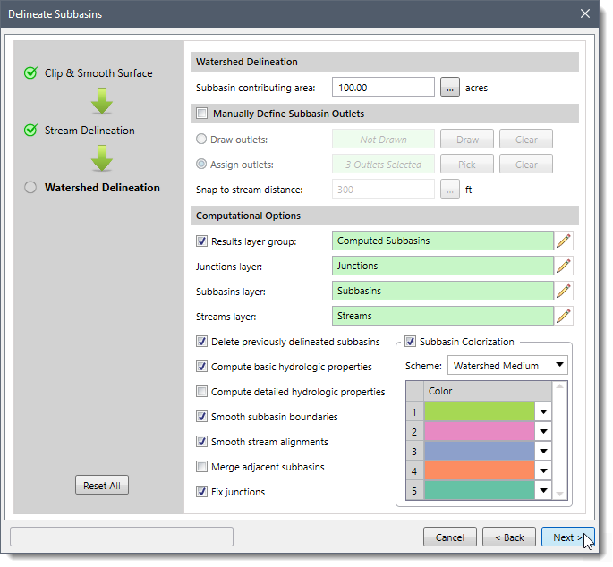
Note that the user can switch back and forth between completed stages and change their choices using the [Back] and [Next] buttons. To reset the entire delineation process, the user can click the [Reset All] button.
To learn more about the basic and detailed hydrologic properties computed during the Watershed Delineation stage, refer to this article in our knowledge base.
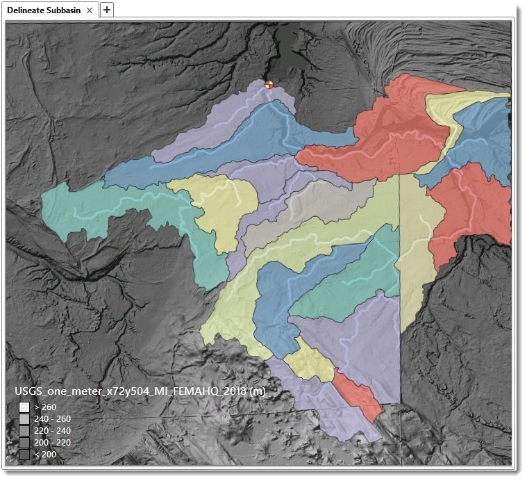
On completion of the Watershed Delineation stage, the delineated subbasins network will be displayed in the Map View.


CivilGEO G2 Reviews
4.8/5.0 Rating, Over 230 Reviews

GeoHECRAS is recognized as the top Civil Engineering Design Software with an average of 4.8 out of 5.0 rating from over 230 real user reviews on G2.


We use cookies to give you the best online experience. By agreeing you accept the use of cookies in accordance with our cookie policy.
When you visit any web site, it may store or retrieve information on your browser, mostly in the form of cookies. Control your personal Cookie Services here.


