
Welcome to CivilGEO Knowledge Base
Welcome to CivilGEO Knowledge Base
Engineers use land cover datasets to assign manning’s n values quickly and account for flow resistance, especially over large areas. It is a popular approach because of its ability to reduce HEC-RAS modeling time, improve data quality, increase data availability in digital format, and improve the ability to manage and visualize geospatial information in GIS.
CivilGEO software allows the users to import land use information in polygon (shapefile) and gridded formats. Additionally, the software allows the user to use the National Land Cover Database (NLCD) web map service to obtain gridded land cover data and automatically compute Manning’s n values based on land cover. The National Land Cover Database provides land cover data for the entire United States. The software can dynamically download an NLCD raster land cover grid for the area being modeled. Each 75ft x 75ft land cover grid cell represents a specific land type. Up to 20 different land types and corresponding Manning’s roughness values are provided.
The user can use user-defined land cover polygon shapefiles or the National Land Cover Database (NLCD) web map service to assign Manning’s roughness to cross sections and 2D flow areas. Furthermore, the user can import multiple land cover layers (NLCD raster grid layer, Manning’s roughness polygons layer, etc.) and merge them into a single composite land cover map layer. The user can later utilize the composite land cover map layer to assign Manning’s roughness to a specific scenario (plan).
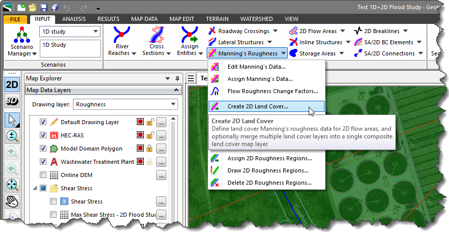
In GeoHECRAS, the Create 2D Land Cover command allows the user to add multiple land use data input files to create a single land use coverage layer. For example, a user may want to use USGS NLCD 2016 gridded land use data as the base land use coverage data. However, a user may also want to use or generate a polygon coverage (shapefile) that is more accurate for many of the areas within the study region (i.e., the main channel regions, buildings, roads, etc.). By setting the more accurate shapefile as the higher priority, the land use data from the shapefile will be used unless it does not cover portions of the specified area, in which case the USGS gridded data will be used for those areas. The software processes the various land use data types, creates a composite land cover layer, and stores it as a GeoTIFF file (a companion *.hdf file generated).
To create a composite 2D land cover layer, follow the steps below:
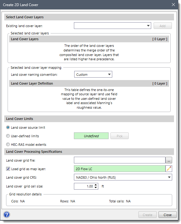
The following sections describe how to create a composite 2D land cover layer and interact with the above dialog box.
The Select Land Cover Layers section allows the user to select the existing land cover layers in the project as well as the NLCD grided land use data in order to merge them into a single composite land cover layer. Furthermore, the user can adjust the priority for merging the land cover layers and define the naming convention for the combined land use data.
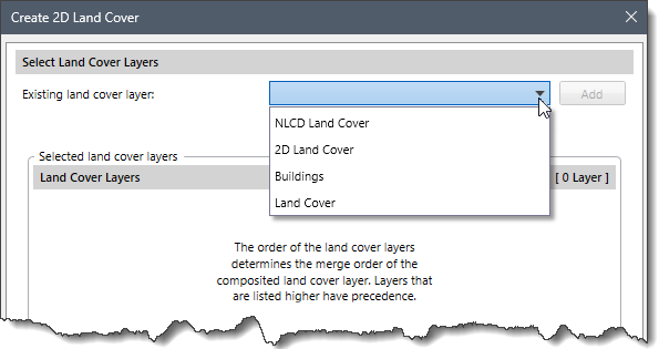
This dropdown combo box allows the user to select one or more land use data layers that will be merged into a single composite land cover layer.
To select one or more land use files of varying types, follow the steps below:
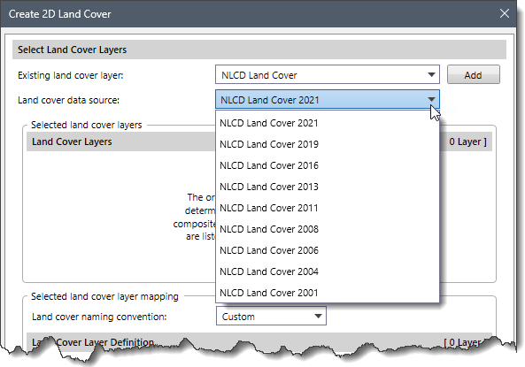
 Note that selecting NLCD Land Cover layer in the Existing land cover layer dropdown combo box entry displays an additional Land cover data source dropdown combo box entry. This dropdown combo box entry allows the user to select which land use data source to utilize for the newly created land cover layer. By default, the software selects the most recent land use data. The following options are available in the dropdown combo box:
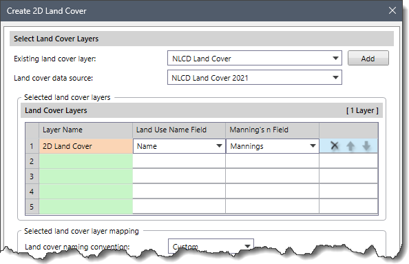
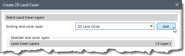
This section displays the source land cover layers that will be merged to create a composite layer in a tabular form. If more than one land use file is selected, the user can use the up and down arrows in the Land Cover Layers table to move the listed files.
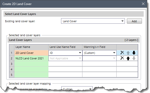 Note that the order of the land cover layers in the table determines the priority of land use data. The layer at the top of the list is granted the highest priority, and so on.
This section allows the user to define the land cover naming convention. Because the software supports multiple land use files and types, the user will have to select one of the established naming conventions or provide a custom naming convention for each land use type.
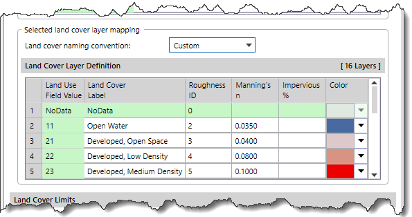
The Land cover naming convention dropdown combo box allows the user to set the naming convention for a shapefile. Currently, there are three options for defining the names of the land use types:
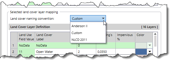
The Land Cover Layer Definition table defines the one-to-one mapping of the source layer Land Use Field Value to the user-defined Land Cover Label and associated Manning’s n value. The software will automatically specify the mapping settings. However, the table cells can be edited (except the layer name) to modify mapping settings.
This section allows the user to define the extent of the land cover grid file to be generated.
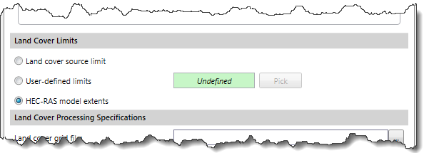 The following options are provided:
This section allows the user to define the processing options for generating the composite land cover grid file.
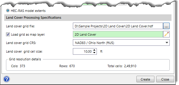
The Land cover grid file input field is used to define the name and the directory address where the composite land cover grid file will be saved.
The Load grid as map layer checkbox causes the software to add the composite land cover layer in the Map Data Layers panel. By default, this checkbox is checked. The software automatically defines the name of this layer based on the land cover grid file name provided by the user. However, the user can change the name to whatever is desired by clicking the pen icon next to this field.
The Land cover grid CRS dropdown combo box allows the user to define the layer’s CRS (Coordinate Reference System). If there is only one CRS in the project, the software automatically selects it.
The Land cover grid cell size spin control button can be used to define the cell size of the land cover grid. By default, the software uses a value of 15 ft.
Based on the defined grid cell size and the extent of land cover, the Grid resolution details section displays the total number of cells and count of columns and rows that the land cover grid file will contain.
Once all the options in the Create 2D Land Cover dialog box are configured, click the [Create] button. The software will combine the source land cover layers to create a single composite land cover grid file at the specified location. If the Load grid as map layer checkbox was left checked, the newly created land cover grid will be added in the Map Data Layers panel.
Once the user has created a land cover layer and added some user-defined classification regions, the user-created 2D land cover as Manning’s roughness can be linked to a specific scenario (plan).
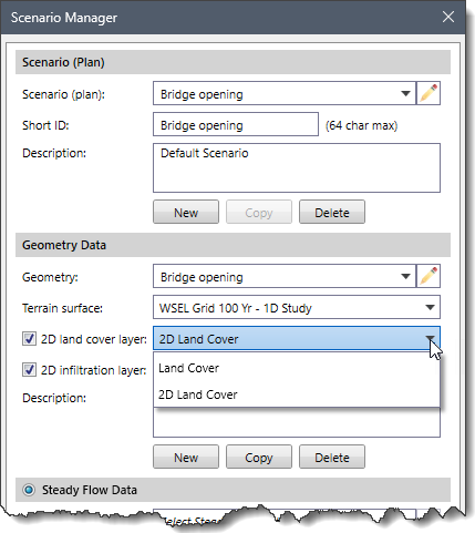
The Scenario Manager command of the Input ribbon menu allows the user to associate a land cover layer as Manning’s roughness to a specific scenario (plan).
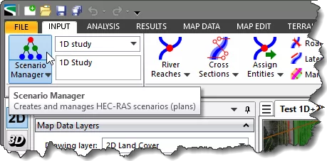
The user can check the 2D land cover layer checkbox and then select the desired layer from the dropdown combo box that will be associated with the selected scenario (plan).
To learn more about the Scenario Manager command, refer to this article in our knowledge base.


CivilGEO G2 Reviews
4.8/5.0 Rating, Over 230 Reviews

GeoHECRAS is recognized as the top Civil Engineering Design Software with an average of 4.8 out of 5.0 rating from over 230 real user reviews on G2.


We use cookies to give you the best online experience. By agreeing you accept the use of cookies in accordance with our cookie policy.
When you visit any web site, it may store or retrieve information on your browser, mostly in the form of cookies. Control your personal Cookie Services here.


