
Welcome to CivilGEO Knowledge Base
Welcome to CivilGEO Knowledge Base
The Conflate Point Data command allows the user to define a buffer distance for the selected cross sections, roadway crossings, lateral structures, inline structures, and SA/2D flow area connections for mapping elevation point data.
This article describes how to use the Conflate Point Data command in GeoHECRAS software. This command can also be used for the HEC-HMS cross sections.
The Conflate Point Data command for cross sections allows survey point data to be merged into cross sections in order to define cross section geometry. This is especially helpful in projects where there is no cross section bathymetry data available for the cutting of cross sections. This command works with XYZ point files, AutoCAD drawings, and GIS point shapefiles.
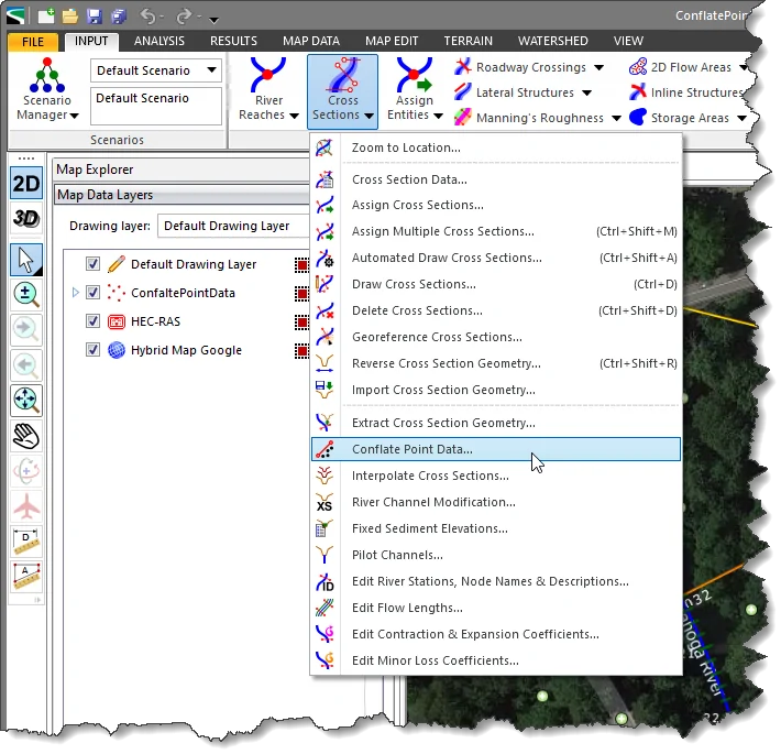
Follow the steps given below to use the Conflate Point Data command:
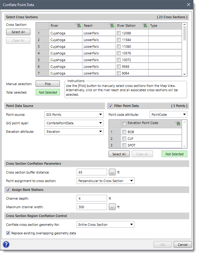
The following sections describe the Conflate Point Data command and how to interact with the above dialog box.
This section is used to manually select the cross sections for mapping elevation point data. If a cross section is already selected on the Map View prior to running this command, the same cross section will be shown selected within the table.
Alternatively, click the [Pick] button to interactively select the cross sections from the Map View. Clicking the [Select All] button causes all the cross sections to be selected. Clicking the [Clear All] button causes all the cross sections to be deselected. The Total selected read-only field will show the number of selected cross sections.
This section is used to define the survey cross section point data source to be used for mapping elevation point data. Depending upon the point data source type that is selected, different options are provided to specify additional point data information.
Clicking the [Select All] button causes all the survey cross section point code to be selected. Clicking the [Clear All] button causes all the survey cross section point code to be deselected.

This optional section is used to construct channel bank locations based upon an assumed normal flow depth entered in the Channel depth entry field and a maximum channel width search distance entered in the Maximum channel width entry field. The software will first determine where the thalweg location is on a cross section. It will then move outward from the thalweg until the requested channel depth is reached within the maximum channel width specified.
The Replace existing overlapping geometry data checkbox option allows the user to replace the existing cross section geometry data with the surveyed cross section data.
Using the Conflate Point Data command of the Inline Structures menu item, the user can map elevation point data to adjacent inline structure weir crest geometry within a buffer area region.
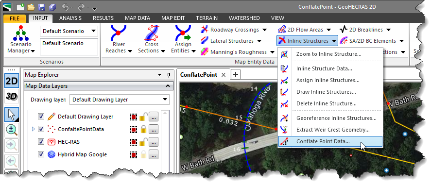
Selecting this command will cause the software to display the following dialog box.

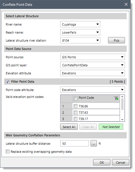
Using the Conflate Point Data command of the Lateral Structures menu item, the user can map elevation point data to adjacent lateral structure weir crest geometry within a buffer area region.
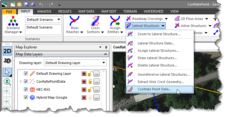
Selecting this command will cause the software to display the following dialog box.
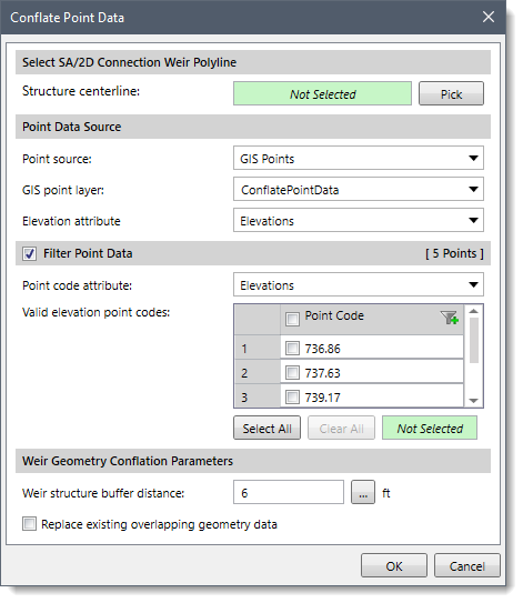
Using the Conflate Point Data command of the SA/2D Connections menu item, the user can map elevation point data to storage area/2D flow area connections weir crest geometry within a buffer area region.
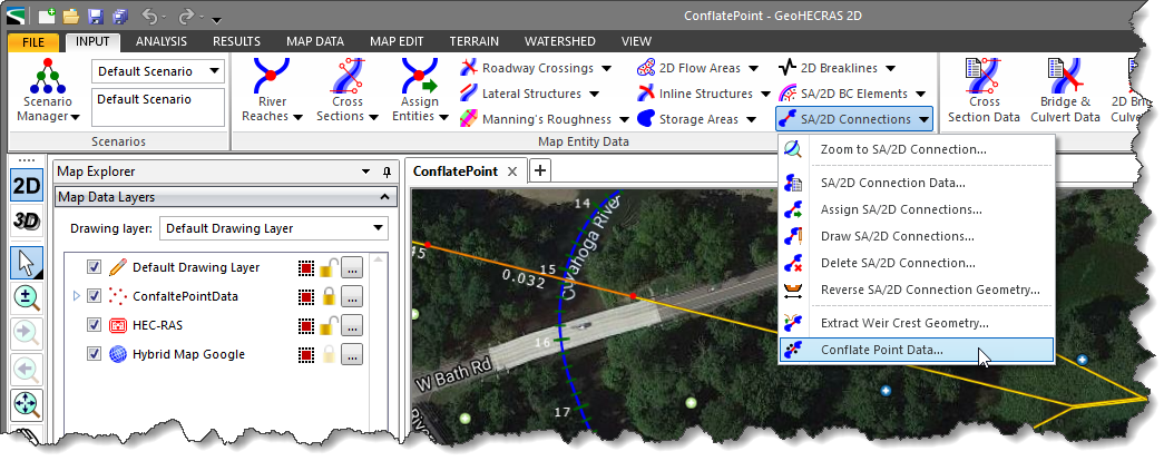
Selecting this command will cause the software to display the following dialog box.
Using the Conflate Point Data command of the Roadway Crossings menu item, the user can map elevation point data to adjacent roadway crossing geometry within a buffer area region.
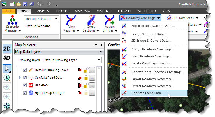
Selecting this command will cause the software to display the following dialog box.
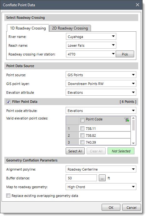
Note that if the model contains only 2D elements, then 1D Roadway Crossing panel will be disabled.


CivilGEO G2 Reviews
4.8/5.0 Rating, Over 230 Reviews

GeoHECRAS is recognized as the top Civil Engineering Design Software with an average of 4.8 out of 5.0 rating from over 230 real user reviews on G2.


We use cookies to give you the best online experience. By agreeing you accept the use of cookies in accordance with our cookie policy.
When you visit any web site, it may store or retrieve information on your browser, mostly in the form of cookies. Control your personal Cookie Services here.


