
Welcome to CivilGEO Knowledge Base
Welcome to CivilGEO Knowledge Base
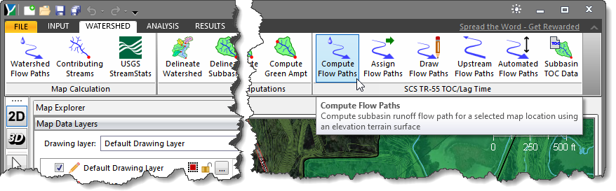
The Compute Flow Paths command computes and traces the subbasin runoff flow path for a selected map location using an elevation terrain surface until the flow path reaches a sink or the edge of the processed DEM grid.
Follow the steps below to use the Compute Flow Paths command:
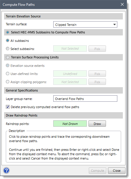
The following sections describe how to use the Compute Flow Paths command and interact with the above dialog box.
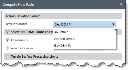
This section allows the user to specify which terrain grid layer should be used. The Terrain surface dropdown combo box lists all the terrain surfaces that are already added to the project. By default, this dropdown combo box lists the same terrain surface used in the Scenario Manager dialog box. If there is no terrain surface selected in the Scenario Manager dialog box and there is only one terrain surface loaded, it will select that terrain surface by default.
The Select HEC-HMS Subbasins to Compute Flow Paths section controls which subbasins should be used to compute flow paths. Select the Select HEC-HMS Subbasins to Compute Flow Paths radio button to enable this section.
The All Subbasins entry causes the software to compute the flow paths for all subbasins on the HEC-HMS layer.
The Select Subbasins entry allows the user to interactively select subbasin polygons from the HEC-HMS layer on the Map View. Clicking on the [Pick] button will cause the dialog box to temporarily disappear and will allow the user to select HEC-HMS subbasin polygons from the Map View. The total number of selected subbasin polygons will be displayed in the entry upon returning to the dialog box.
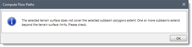
Note that the Compute Flow Paths command confirms that the selected subbasins overlay the selected elevation grid terrain surface. If not, the software will display the following message.
If one subbasin was selected:
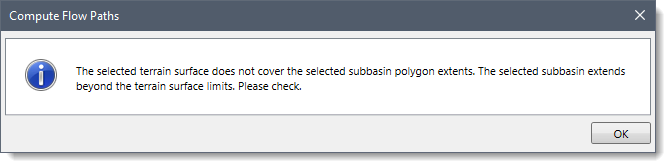
If more than one subbasin was selected:
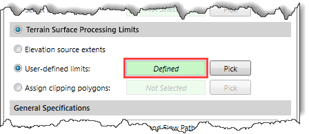
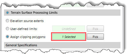
This section allows the user to define the area extent of the terrain surface that will be used to compute the flow paths. Select the Terrain Surface Processing Limits radio button to enable this section.
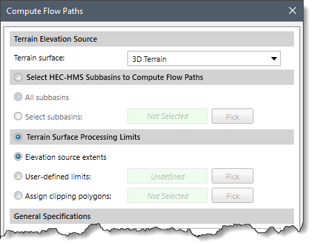
The user can select from three available options, as described below:
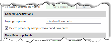
This section allows the user to define the name of the layer group in the Layer group name input field. This name identifies the layer group that will be created in the Map Data Layers panel that will contain the raindrop points, downstream overland flow paths, and main streams. The Delete previously computed overland flow paths checkbox can be checked to delete any previously computed runoff flow paths.
This section allows the user to draw the raindrop points on the Map View.
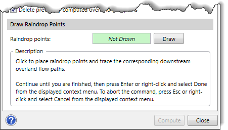
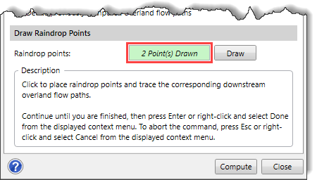
Click the [Draw] button to draw the raindrop points. The Compute Flow Paths dialog box will temporarily disappear, and a prompt will be displayed on the status bar instructing the user to place the raindrop point(s). Click on the Map View to place the raindrop point(s). Note that the number of raindrop points will be displayed on the status bar. Once finished, press the [Enter] key or right-click and select Done from the displayed context menu. To abort the command, press the [Esc] key or right-click and select Cancel from the displayed context menu. Any drawn raindrop points added during the command session will be removed. The Compute Flow Paths dialog box will be redisplayed, and the total number of selected raindrop points will be displayed in the Raindrop points entry, as shown below.
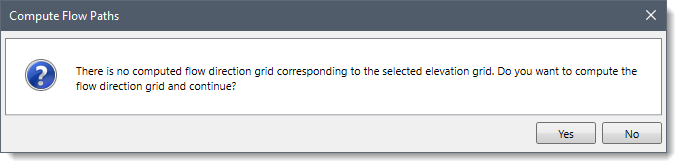
After defining all the required fields, click on the [Compute] button. The Compute Flow Paths confirmation dialog box will be displayed. Click the [Yes] button to compute the flow direction grid. To cancel the process, click the [No] button.
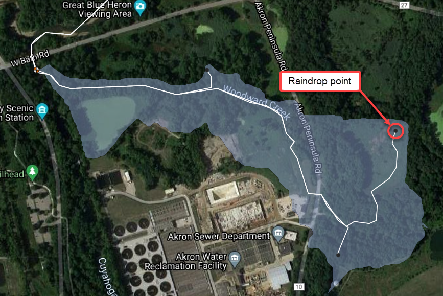
The software will then internally compute the downstream flow path from each raindrop point that will merge into a major stream. Once the process is complete, the overland flow path from each raindrop point will be displayed on the Map View as shown below.
Note that while the computation is running, the [Close] button changes to [Cancel] so that the user can abort the computation process if desired.
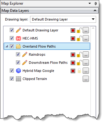
In the Map Data Layers panel, the software provides a data legend for the computed flow paths layer, which lists the raindrop points and downstream overland flow paths included within that layer. The user can expand the layer to view the data legend.


CivilGEO G2 Reviews
4.8/5.0 Rating, Over 230 Reviews

GeoHECRAS is recognized as the top Civil Engineering Design Software with an average of 4.8 out of 5.0 rating from over 230 real user reviews on G2.


We use cookies to give you the best online experience. By agreeing you accept the use of cookies in accordance with our cookie policy.
When you visit any web site, it may store or retrieve information on your browser, mostly in the form of cookies. Control your personal Cookie Services here.


