HEC‑RAS and HEC‑2 are both software programs that are used for computing water surface elevations for rivers, streams, and other open channel networks. While both software programs were developed by the Army Corps of Engineers, the two software programs are completely different. None of the computational routines in the HEC‑2 program were used in the HEC‑RAS software. When HEC‑RAS was being developed, a significant effort was spent improving the computational capabilities of the HEC‑2 program. Because of this, there are computational differences between the two programs.

This article describes all of the major areas in which computational differences can occur between the two software programs.
Cross Section Conveyance Calculations
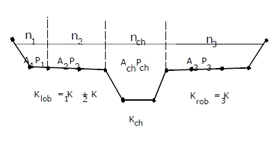
Both HEC‑RAS and HEC‑2 utilize the standard step method for balancing the energy equation to compute a water surface for a cross section. A key element in the solution of the energy equation is the calculation of conveyance. The conveyance is used to determine friction losses between cross sections, the flow distribution at a cross section, and the velocity weighing coefficient alpha. The approach used in HEC‑2 is to calculate conveyance between every coordinate point in the cross section overbank (as show in the first figure). The conveyance is then summed to get the total left overbank and right overbank values. HEC‑2 does not subdivide the main channel for conveyance calculations. This method of computing overbank conveyance can lead to different amounts of total conveyance when additional points are added to the cross section, without actually changing the geometry.
The HEC‑RAS program supports this method for calculating conveyance, but the default method is to make conveyance calculations only at n‑value break points, as shown in below given figure.

Testing Using HEC‑2 Conveyance Calculation Approach
Comparisons of HEC‑RAS results with those from HEC‑2 were performed using 97 data sets from the HEC profile accuracy study (HEC, 1986). Water surface profiles were computed for 10% and 1% chance floods using HEC‑2 and HEC‑RAS, both programs using the HEC‑2 approach for computing overbank conveyance. The below table shows the water surface difference in percentage, for approximately 2000 cross sections, within ±0.02 feet (±6 mm). For the 10% chance flood, 53 cross sections had differences greater than ±0.02 feet (±6 mm). For those cross sections, 62.2% were caused by differences in computation of critical depth and 34% resulted from propagation of the difference upstream. For the 1% chance flood, 88 cross sections had elevation differences over ±0.02 feet (6 mm), of which 60.2% resulted from critical depth and 36.4% from the upstream propagation of downstream differences. HEC‑RAS uses 0.01 feet (3 mm) for the critical depth error criterion, while HEC‑2 uses 2.5% of the depth of flow.
Table: Computed Water Surface Elevation Difference (HEC‑RAS and HEC‑2)
| Difference (feet) |
‑0.02 |
‑0.01 |
0 |
0.01 |
0.02 |
Total |
| 10% Chance Flood |
0.80% |
11.20% |
73.10% |
11.20% |
0.60% |
96.90% |
| 1% Chance Flood |
2.00% |
11.60% |
70.10% |
10.80% |
1.30% |
95.80% |
Testing Using HEC‑RAS and HEC‑2 Approach
The two methods for computing conveyance will produce different answers whenever portions of the overbanks have ground sections with significant vertical slopes. In general, the HEC‑RAS default approach will provide a lower total conveyance for the same elevation and, therefore, a higher computed water surface elevation. In order to test the significance of the two ways of computing conveyance, comparisons were performed using the same 97 data sets. Water surface profiles were computed for the 1% chance event using the two methods for computing conveyance in HEC‑RAS. The results confirmed that the HEC‑RAS default approach will generally produce a higher computed water surface elevation. Out of the 2048 cross section locations, 47.5% had computed water surface elevations within 0.10 feet (30.5 mm), 71% within 0.20 feet (61 mm), 94.4% within 0.40 feet (122 mm), 99.4% within 1.0 feet (305 mm), and one cross section had a difference of 2.75 feet (0.84 m). Because the differences tend to be in the same direction, some effects can be attributed to propagation.
The results from these comparisons do not show which method is more accurate, they only show differences. In general, it is felt that the HEC‑RAS default method is more commensurate with the Manning equation and the concept of separate flow elements. The default method in HEC‑RAS is also more consistent, in that the computed conveyance is based on the geometry, and not on how many points are used in the cross section. Further research, with observed water surface profiles, will be needed to make any final conclusions about the accuracy of the two methods.
Critical Depth Calculations
During the water surface profile calculations, each of the two programs may need to calculate critical depth at a cross section if any of the following conditions occur:
- The supercritical flow regime has been specified by the user.
- The calculation of critical depth has been requested by the user.
- The current cross section is an external boundary cross section and critical depth must be determined to ensure the user defined a boundary condition that is in the correct flow regime.
- The Froude number check for a subcritical profile indicates that critical depth needs to be determined to verify the flow regime of the computed water surface elevation.
- The program could not balance the energy equation within the specified tolerance before reaching the maximum number of iterations.
The HEC‑RAS program has two methods for calculating critical depth:
- Parabolic method
- Secant method
The HEC‑2 program has one method computing critical depth, which is very similar to the HEC‑RAS parabolic method. The parabolic method is computationally faster, but it is only able to locate a single minimum energy. For most cross sections there will only be one minimum on the total energy curve; therefore, the parabolic method has been set as the default method for HEC‑RAS (the default method can be changed from the user interface). If the parabolic method is tried and it does not converge, then the HEC‑RAS program will automatically try the secant method. The HEC‑RAS version of the parabolic method calculates critical depth to a numerical accuracy of 0.01 feet, while HEC‑2’s version of the parabolic method calculates critical depth to a numerical accuracy of 2.5 percent of the flow depth. This, in its self, can lead to small differences in the calculation of critical depth between the two programs.
In certain situations it is possible to have more than one minimum on the total energy curve. Multiple minimums are often associated with cross sections that have breaks in the total energy curve. These breaks can occur due to very wide and flat overbanks, as well as cross sections with levees and ineffective flow areas. When the parabolic method is used on a cross section that has multiple minimums on the total energy curve, the method will converge on the first minimum that it locates. This approach can lead to incorrect estimates of critical depth in that the returned value for critical depth may be the top of a levee or an ineffective flow elevation. When this occurs in the HEC‑RAS program, the software automatically switches to the secant method. The HEC‑RAS secant method is capable of finding up to three minimums on the energy versus depth curve. Whenever more than one minimum energy is found, the program selects the lowest valid minimum energy (a minimum energy at the top of a levee or ineffective flow elevation is not considered a valid critical depth solution).
Given that HEC‑RAS has the capability to find multiple critical depths, and detect possible invalid answers, the final critical depth solutions between HEC‑2 and HEC‑RAS could be quite different. In general the critical depth answer from the HEC‑RAS program will always be more accurate than HEC‑2.
Bridge Hydraulic Computations
A vast amount of effort has been spent on the development of the new bridge routines used in the HEC‑RAS software. The bridge routines in HEC‑RAS allow the modeler to analyze a bridge by several different methods with the same bridge geometry. The model utilizes four user-defined cross sections in the computations of energy losses due to the structure. Cross sections are automatically formulated inside the bridge on an as needed basis by combining the bridge geometry with the two cross sections that bound the structure.
The HEC‑2 program requires the user to use one of two possible methods, the special bridge routine or the normal bridge routine. The data requirements for the two methods are different, and therefore the user must decide prior to defining the model on which method to use.
Differences between the HEC‑2 and HEC‑RAS bridge routines are addressed below.
HEC‑2 Special Bridge Methodology
The largest computational differences will be found when comparing the HEC‑2 special bridge routine results to the equivalent HEC‑RAS bridge results. The following list details these differences:
- The HEC‑2 special bridge routine use a trapezoidal approximation for low flow calculations (Yarnell equation and class B flow check with the momentum equation). The HEC‑RAS program uses the actual bridge opening geometry for all of the low flow methodologies.
- Also for low flow, the HEC‑2 program uses a single pier (of equivalent width to the sum total width of all piers) placed in the middle of the trapezoid. In the HEC‑RAS software, all of the piers are defined separately and the hydraulic computations are performed by evaluating the water surface and impact on each pier individually. While this is more data for the user to enter, the results are much more physically based.
- For pressure flow calculations, HEC‑2 requires the net flow area of the bridge opening. The HEC‑RAS software calculates the area of the bridge opening from the bridge and cross section geometry. Because of the potential error involved in calculating the bridge opening area by hand, differences between the programs may occur for pressure flow calculations.
- The HEC‑RAS software has two equations that can be used for computing pressure flow. The first equation is for a fully submerged condition (i.e. when both the upstream side and downstream side of the bridge is submerged). The fully submerged equation is also used in HEC‑2. A second equation is available in HEC‑RAS, which is automatically applied when only the upstream side of the bridge is submerged. This equation computes pressure flow as if the bridge opening were acting as a sluice gate. The HEC‑2 program only has the fully submerged pressure flow equation. Therefore, when only the upstream side of the bridge is submerged, the two programs will compute different answers for pressure flow because they will be using different equations.
- When using the HEC‑2 special bridge routine, it is not possible for the user to specify bridge low chord geometry data in the bridge table (BT data). The bridge table information is only used for weir flow computations in HEC‑2. When HEC‑2 special bridge data is imported into HEC‑RAS, the user must define the low chord geometry information in order to define the bridge opening. This is due to the fact that the trapezoidal approximation used in HEC‑2 is not used in HEC‑RAS, and therefore the bridge opening geometry must be re-entered.
- When entering bridge table (BT records) geometry information in the HEC‑2 special bridge method, the user had to enter stations that followed along the ground in the left overbank, then across the bridge deck/road embankment; and then along the ground of the right overbank. This was necessary in order for the left and right overbank area to be used in the weir flow calculations. In HEC‑RAS this is not necessary. The bridge deck/roadway information only needs to reflect the additional blocked out area that is not part of the ground. HEC‑RAS will automatically merge the ground geometry information and the high chord geometry data of the bridge deck/roadway.
HEC‑2 Normal Bridge Methodology
In general importing HEC‑2 normal bridge data into HEC‑RAS should not cause any problems. The HEC‑RAS program automatically selects the appropriate energy‑based method for low flow and high flow conditions, which is equivalent to the HEC‑2 normal bridge method. The following list details possible differences that may occur:
- In HEC‑2 the bridge pier information is either entered as part of the bridge table (BT data) geometry or the ground geometry information (GR data). If the user stays with the energy based methods in HEC‑RAS, the computational results should be about the same. If the user wishes to use either the Momentum or Yarnell methods for low flow, they must first delete the pier geometry information from the BT or GR data, and then re‑enter the pier information in HEC‑RAS. If this is not done, HEC‑RAS will not know about the pier information, and will therefore incorrectly calculate the losses with either the Momentum or Yarnell methods.
- The HEC‑2 Normal bridge method utilizes six cross sections. HEC‑RAS uses only four cross sections in the vicinity of the bridge. The two cross sections inside the bridge are automatically formulated from the cross sections outside the bridge and the bridge geometry. In general, it is common for HEC‑2 modelers to repeat cross sections through the bridge opening (i.e., the cross sections used inside the bridge were a repeat of the downstream section). If however, the HEC‑2 modelers entered completely different cross sections inside the bridge than outside, the HEC‑RAS software will add two additional cross sections just outside of the bridge, in order to get the correct geometry inside of the bridge. This gives the HEC‑RAS data set two more cross‑sections than the original HEC‑2 data set. The two cross sections are placed at zero distance from the bridge, but could still cause some additional losses due to contraction and expansion of flow. The user may want to make some adjustments to the data when this happens.
- In HEC‑2 the stationing of the bridge table (BT Records) had to match stations on the ground (GR Records) data. This is not required in HEC‑RAS. The stationing of the data that makes up a bridge geometry (ground, deck/roadway, piers, and abutments) does not have to match in anyway; HEC‑RAS will interpolate any points that it needs.
Culvert Hydraulic Computations
The culvert routines in HEC‑RAS and HEC‑2 were adapted from the Federal Highway Administrations Hydraulic Design of Highway Culverts publication, HDS No. 5 (FHWA, 1985). The following is a list of the differences between the two programs.
- HEC‑2 can only perform culvert calculations for box and circular culvert shapes. HEC‑RAS can handle the following shapes: box; circular pipe; semi‑circle; arch; pipe arch, vertical ellipse; horizontal ellipse; low profile arch; high profile arch; and ConSpan.
- HEC‑RAS also has the ability to mix the culvert shapes, sizes, and all other parameters at any single culvert crossing. In HEC‑2 the user is limited to the same shape and size barrels.
- HEC‑RAS has the ability to use two roughness coefficients inside the culvert barrel (one for the top and sides, and one for the bottom). This allows for better modeling of culverts that have a natural bottom, or culverts that were designed for fish passage.
- HEC‑RAS allows the user to fill in a portion of a culvert. This allows users to model culverts that are buried.
Floodway Encroachment Calculations
The floodway encroachment capabilities in HEC‑RAS were adapted from those found in HEC‑2. For the most part, encroachment methods 1‑3 in HEC‑RAS are the same as methods 1‑3 in HEC‑2. The following is a list of the differences between the two programs.
- HEC‑RAS has an additional capability of allowing the user to specify a left and right encroachment offset. While in general the encroachments can go all the way up to the main channel bank stations, the offset establishes an additional buffer zone around the main channel bank stations for limiting the encroachments. The offset is applicable to methods 2‑5 in HEC‑RAS.
- The logic of method 4 in HEC‑RAS is the same as method 4 in HEC‑2. The only difference is that the HEC‑RAS method 4 will locate the final encroachment to an accuracy of 0.01 feet, while the HEC‑2 method 4 uses a parabolic interpolation method between the existing cross section points. Since conveyance is non‑linear with respect to the horizontal stationing, the interpolation in HEC‑2 may not always find the encroachment station as accurately as HEC‑RAS.
- Method 5 in HEC‑RAS is a combination of HEC‑2’s methods 5 and 6. The HEC‑RAS method 5 can be used to optimize for a change in water surface (HEC‑2 method 5); a change in energy (HEC‑2 method 6); or both parameters at the same time.
- At bridges and culverts, the default in HEC‑RAS is to perform the encroachment, while in HEC‑2 the default was not to perform the encroachment. Both programs have the ability to turn encroachments at bridges and culverts on or off.
- At bridges where the energy-based modeling approach is being used (similar to HEC‑2’s normal bridge method), HEC‑RAS will calculate the encroachment for each of the cross sections through the bridge individually. HEC‑2 will take the encroachments calculated at the downstream side of the bridge and fix those encroachment stations the whole way through the bridge.
- In HEC‑2, if the user specifies a fixed set of encroachments on the X3 record, this would override anything on the ET record. In HEC‑RAS, when the data is imported the X3 record, encroachments are converted into blocked obstructions. Therefore any additional encroachment information found on the ET record will be used in addition to the blocked obstructions.
New Computational Features in HEC‑RAS
- HEC‑RAS can perform subcritical, supercritical, or mixed flow regime calculations all in a single execution of the program. The cross section order does not have to be reversed (as in HEC‑2), the user simply selects the computational flow regime. When in a mixed flow regime mode, HEC‑RAS will also locate hydraulic jumps.
- HEC‑RAS has the ability to perform multiple bridge and/or culvert openings at the same roadway crossing.
- At bridges, the user has the ability to use a momentum‑based solution for class A, B, and C low flow. In HEC‑2 the momentum equation was used for class B and C flow, and requires the trapezoidal approximation. The HEC‑RAS momentum solution also takes into account friction and weight forces that HEC‑2 does not.
- HEC‑RAS can model single reaches, dendritic stream systems, or fully looped network systems. HEC‑2 can only do single reaches and a limited number of tributaries (up two three stream orders).
- At stream junctions, HEC‑RAS has the ability to perform the calculations with either an energy‑based method or a momentum-based method. HEC‑2 only has the energy-based method.
- HEC‑RAS has the following new cross section properties not found in HEC‑2: blocked ineffective flow areas; normal ineffective flow areas can be located at any station (in HEC‑2 they are limited to the main channel bank stations); blocked obstructions; and specification of levees.
- In HEC‑RAS the user can enter up to 500 points in a cross section. HEC‑2 has a limit of 100.
- HEC‑RAS has the ability to perform geometric cross section interpolation. HEC‑2 interpolation is based on a ratio of the current cross section and a linear elevation adjustment.
- HEC‑RAS has an improved flow distribution calculation routine. The new routine can subdivide the main channel as well as the overbanks, and the user has control over how many subdivisions are used. The HEC‑2 flow distribution option is limited to the overbank areas and breaks at existing coordinate points.


