
Welcome to CivilGEO Knowledge Base
Welcome to CivilGEO Knowledge Base
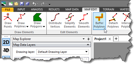
The Buffer Polylines command of CivilGEO’s software allows the user to create new polygons around the selected polylines using a specified buffer distance.
Note that the user can also create a buffer around selected polygons using the Buffer Polygons command. To learn more about this command, refer to this article in our knowledge base.
Buffered features are stored in user-specified target layers, which must contain either line or polygon features. For instance, the user might use buffers to show an ecological zone around a waterway or the area around a contaminated well. More than one feature can be buffered at once, but a separate buffer will be created around each feature.
Follow the steps below to use the Buffer Polylines command:
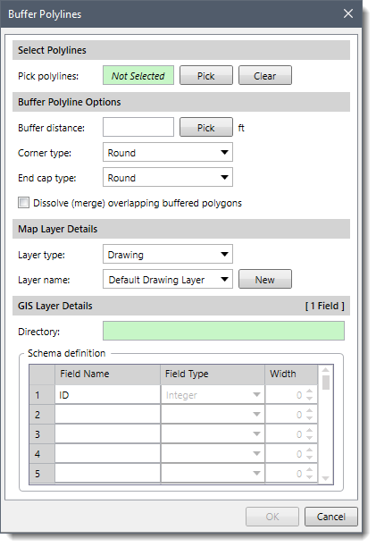
The following sections describe the Buffer Polylines command and how to interact with the above dialog box.
The Select Polylines section allows the user to select polylines to buffer from the Map View. The user can click the [Pick] button to select polylines from the Map View.
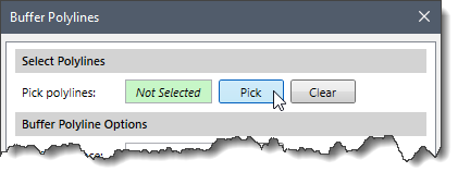
After selecting the polylines, the number of selected polylines will be displayed in the Pick polylines read-only field. Note that if polylines were pre-selected prior to running this command, then the Pick polylines read-only field will display the number of selected polylines.
The user can click the [Clear] button to cancel any previous selection and redo the entire process.
This section allows the user to specify the buffer distance, corner type and shape of the buffer at the end of the polylines.
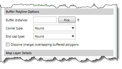
The following entries are provided in this section:
This section allows the user to create a new general drawing layer or a GIS layer for the buffer polygons. By default, the software places the buffer polygons in the Default Drawing Layer. When creating a GIS layer, the polygons are saved as a shapefile.
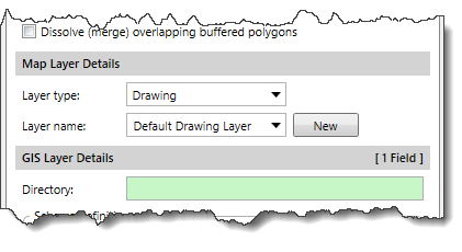
The following entries are provided in this section to define the type and name of the map layer:
This section gets enabled when the user selects a GIS layer type. Otherwise, the options in this section are not available.
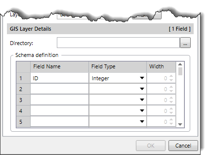
The Directory field defines the path and name of the shapefile to be created. The user can click the […] browse button to select the shapefile directory and file name.
The Schema definition data table allows the user to define the fields to include for the shapefile layer.
This data table requires the following data:
When all the data have been defined in the dialog box, the user can click the [OK] button and the software will create buffer polygons around the selected polylines.


CivilGEO G2 Reviews
4.8/5.0 Rating, Over 230 Reviews

GeoHECRAS is recognized as the top Civil Engineering Design Software with an average of 4.8 out of 5.0 rating from over 230 real user reviews on G2.


We use cookies to give you the best online experience. By agreeing you accept the use of cookies in accordance with our cookie policy.
When you visit any web site, it may store or retrieve information on your browser, mostly in the form of cookies. Control your personal Cookie Services here.


