
Welcome to CivilGEO Knowledge Base
Welcome to CivilGEO Knowledge Base
Boundary conditions are an important part of hydraulic modeling as they allow hydraulic modeling programs such as GeoHECRAS to begin performing calculations. In GeoHECRAS, boundary conditions for steady and unsteady flow analysis are entered using the Steady Flow Data and Unsteady Flow Data commands, respectively.
Steady flow data is required to perform a steady water surface profile calculation. Steady flow data consists of flow regime, boundary conditions, and discharge information (peak flows or flow data from a specific period in time).
Steady flow analysis can be run with a subcritical, supercritical, or mixed flow regime. Depending on the flow regime, the user is required to enter an upstream boundary condition, a downstream boundary condition, or both. Boundary conditions are necessary to establish the starting water surface at the ends of the river systems (upstream and downstream). A starting water surface is necessary for the program to begin calculations.
For a subcritical flow regime, boundary conditions are only necessary at the downstream ends of the river system. For supercritical flow regime, boundary conditions are only necessary at the upstream ends of the river system. For mixed flow regime, boundary conditions must be entered at all ends of the river system.
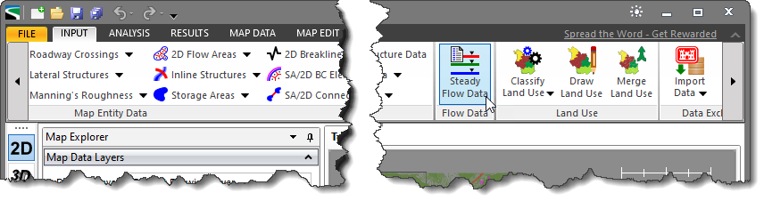
To enter boundary conditions for the steady flow analysis, select the Steady Flow Data command from the Input ribbon menu.
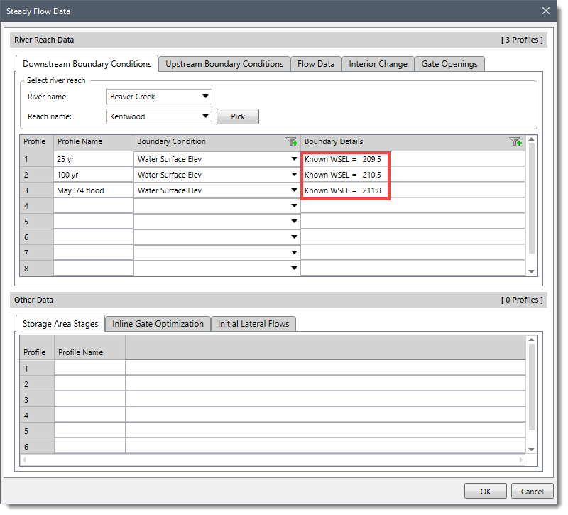
The Steady Flow Data dialog box will be displayed.
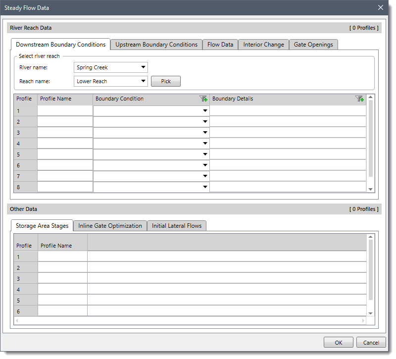
The Steady Flow Data dialog box has separate panels for entering downstream and upstream boundary conditions. Every river and the corresponding reach in the project are listed under the Select river reach section. Each reach has an upstream and downstream boundary condition. After selecting the reach for which boundary conditions are to be entered, the user can enter the boundary conditions for numerous profiles in the table displayed in the corresponding Upstream Boundary Conditions and Downstream Boundary Conditions panels.
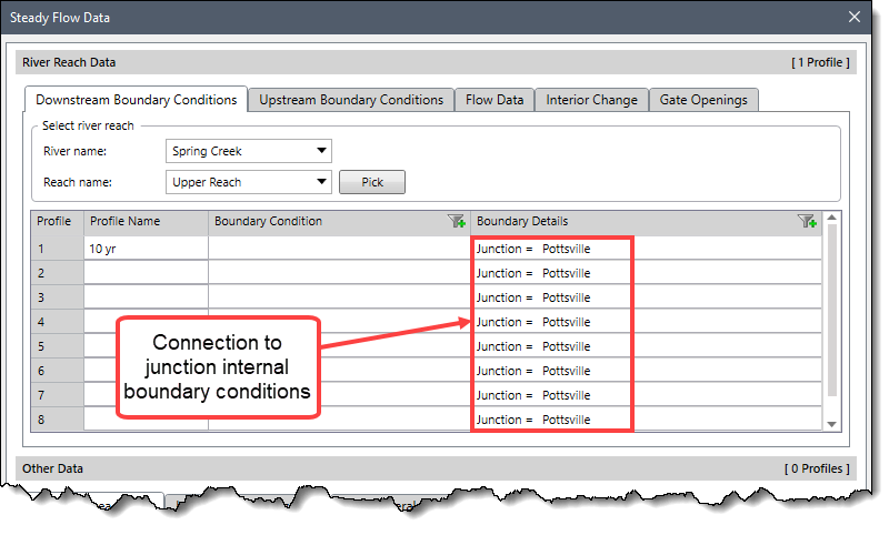
Note that connections to junctions are considered internal boundary conditions. Internal boundary conditions are automatically listed in the table, based on how the river system was defined. The user is only required to enter the necessary external boundary conditions.
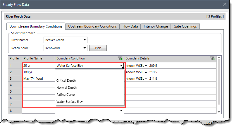
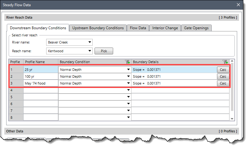
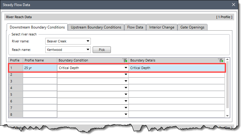
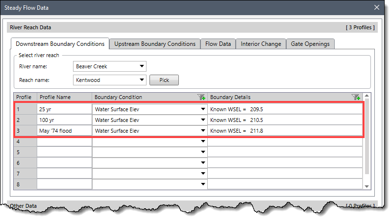
To define the external boundary condition, select the cell location in which you would like to enter a boundary condition. Define the profile name under the Profile Name column. Select the type of boundary condition from within the Boundary Condition column. There are four external boundary conditions available for steady flow analysis: Known Water Surface Elevations, Critical Depth, Normal Depth, and Rating Curve.
 For the selected boundary conditions, enter the corresponding boundary condition data under the Boundary Details column.
Unsteady flow data are required to perform an unsteady flow analysis. Unsteady flow data consists of both external and internal boundary conditions. External boundary conditions are required to run an unsteady model. External boundary conditions must be established at all the open ends of the river system being modeled. These are the boundary conditions you must add to the upstream and downstream ends of each reach (or 2D flow area). Internal boundary conditions are optional and allow the user to define gate operations and add flow within a river reach.
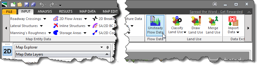
To enter the boundary conditions for unsteady flow analysis, select the Unsteady Flow Data command from the Input ribbon menu.
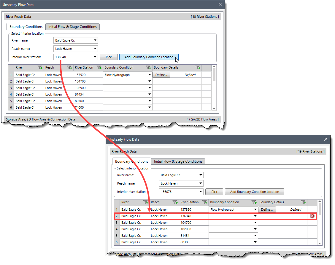
The Unsteady Flow Data dialog box will be displayed. In this dialog box, the river, reach and river station locations of the external bounds as well as any gated structures that are defined within the system (inline, lateral, or between storage areas and/or 2D flow areas) of the system will be automatically entered into the table. Any SA/2D flow areas, boundary condition lines, and connection gate locations in the project will be listed under the tables shown under the Storage Area, 2D Flow Area & Connection Data sections.
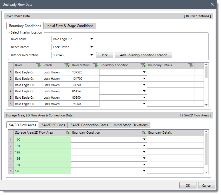
The user can select the desired boundary condition type for the selected location using dropdown combo boxes provided under the Boundary Condition column. Not all boundary condition types are available for use at all locations. The software automatically filters out and lists only those boundary conditions that are relevant to the selected location. After selecting the boundary condition type, the user can define the boundary condition data by clicking the [Define] button.
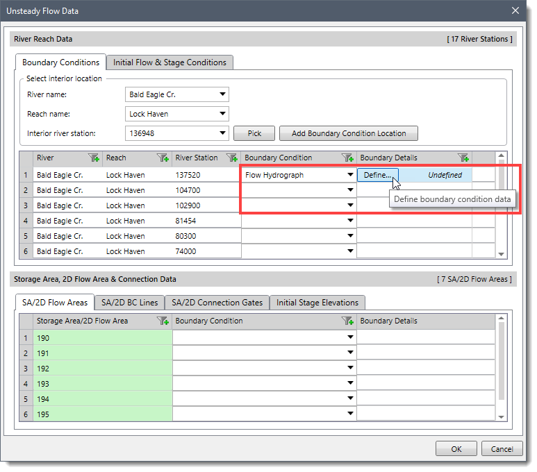
Clicking on the [Define] button causes the software to open a dialog box (each of which is illustrated in the next section) corresponding to the selected boundary condition where the user can enter the boundary condition data. Once the boundary condition data is defined, the status of the corresponding cell changes from Undefined to Defined.
The GeoHECRAS software also allows the user to add additional river station locations for entering internal boundary conditions. To add an additional river station location, select the river station from the Interior river station dropdown combo box and then click the [Add Boundary Condition Location] button. The selected river station location along with the corresponding river and reach will be added to the table.
Several different types of boundary conditions are available to users for steady and unsteady flow analysis. For unsteady flow analysis, there are also several internal boundary conditions. The below table summarizes all available boundary conditions.
| Boundary Conditions | Upstream or Downstream? | Internal or External? | Steady or Unsteady? |
|---|---|---|---|
| Normal Depth | Both for steady, downstream for unsteady | External | Both |
| Critical Depth | Both | External | Steady |
| Known Water Surface Elevation | Both | External | Steady |
| Rating Curve | Both for steady, downstream for unsteady | External | Both |
| Stage Hydrograph | Both | External | Unsteady |
| Flow Hydrograph | Both | External | Unsteady |
| Stage/Flow Hydrograph | Both | External | Unsteady |
| Lateral Inflow Hydrograph | N/A | Internal | Unsteady |
| Uniform Lateral Inflow | N/A | Internal | Unsteady |
| Groundwater Interflow | N/A | Internal | Unsteady |
| Time Series Gate Openings | N/A | Internal | Unsteady (Gates) |
| Elevation Controlled Gates | N/A | Internal | Unsteady (Gates) |
| Internal Boundary Condition Stage/Flow Hydrograph | N/A | Internal | Unsteady (Inline Weir) |
| Precipitation | N/A | N/A | Unsteady |
The normal depth is the most widely used boundary condition for both steady and unsteady flow analysis. For this type of boundary condition, the user is required to enter the energy slope value. This value is used to calculate normal depth (Manning’s equation) at that location. A normal depth can be calculated for each profile based on the user-entered slope. If the energy is unknown, the user could approximate it by clicking the [Calc] button. When applying this boundary condition, it should be placed far enough downstream, such that any errors it produces will not affect the results at the study reach.
In critical depth boundary conditions, the user is not required to enter any further information. The software automatically calculates critical depth for each of the profiles and uses that as the boundary condition. However, critical depth does not occur very often in streams or channels. Using critical depth is only appropriate if there is a significant elevation change or drop structure. It does not matter if you use critical depth as long as your model extends far enough upstream or downstream of the area of interest.
The known water surface elevation boundary condition is typically based on observed data. Alternatively, the user may enter a known water surface elevation to make the current model consistent with another existing model. Just make sure the water surface elevation that is entered into the model is referenced to the correct vertical datum.
The rating curve boundary condition can be used as a downstream boundary condition. Rating curve boundary conditions are typically used where a channel or stream flows into a pond or lake. Rating curves can be constructed using the data available on the United States Geological Survey (USGS) website. Alternatively, one can develop a steady-state model to produce a rating curve.
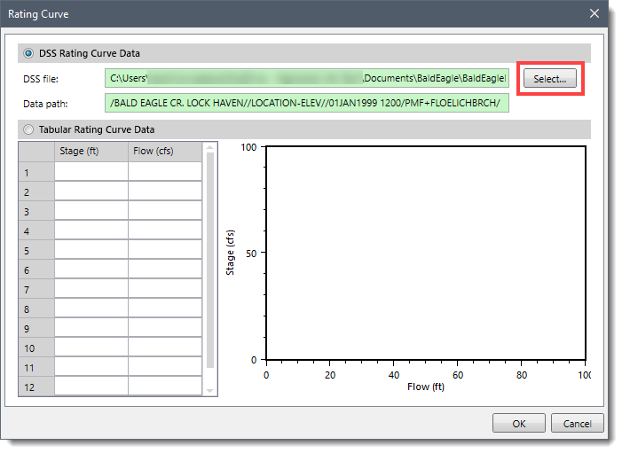
The user can enter the boundary condition data for the rating curve boundary condition type in the Rating Curve dialog box. The user can either read the rating curve data from HEC-DSS or enter it manually into the editor. To read the rating curve data from the DSS file, the user needs to enable the DSS Rating Curve Data section and click the [Select] button.
Clicking on the [Select] button will cause the software to open the DSS Data File & Path dialog box.
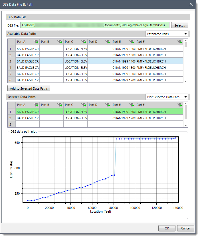
In the above dialog box, the [Select] button allows the user to browse to the location where the desired DSS file is located and select it. Once a DSS file is selected, a list of all of the DSS pathnames within that file will show up in the table. The user can select the desired data path from the table and then click the [Add to Selected Data Paths] button to add the selected data path in the Selected Data Path list. The dialog box also displays the graphical plot for the selected data path in the DSS data path plot section.
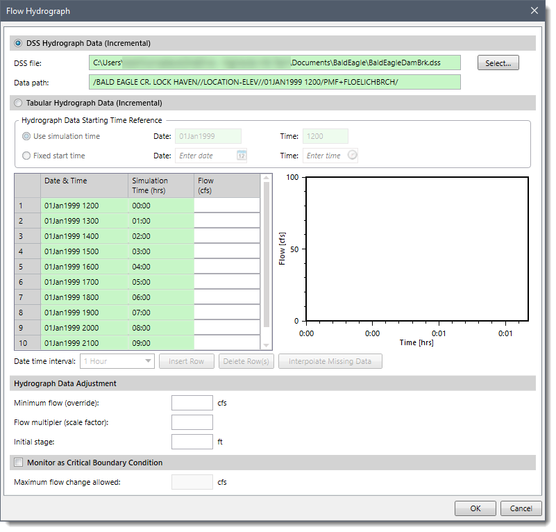
A flow hydrograph can be used as either an upstream boundary or downstream boundary condition, but it is most commonly used as an upstream boundary condition. The user can enter the boundary condition data for the flow hydrograph boundary condition type in the Flow Hydrograph dialog box. The user can either read the data from an HEC-DSS (HEC Data Storage System) file as done in case of a rating curve boundary condition, or enter the hydrograph ordinates manually into a table.
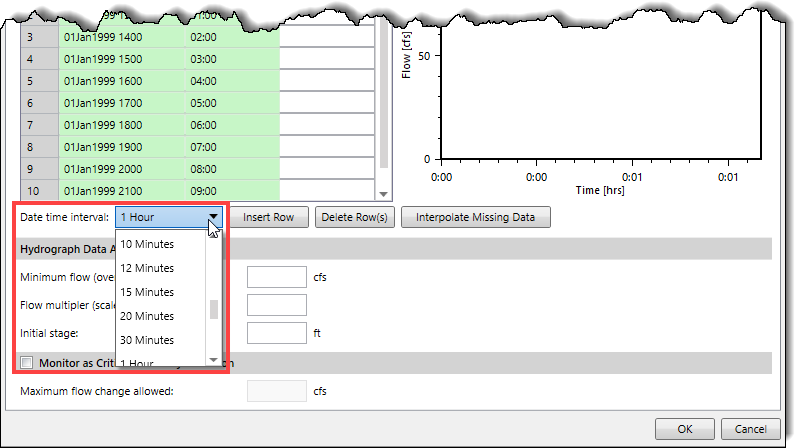
To enter the hydrograph ordinates manually, the user needs to first select the appropriate date-time interval from the list of allowable time intervals shown in the Date time interval dropdown combo box. Currently, the software only supports regular interval time series data.
To enter data into the table, the user is required to select either the Use Simulation Time or Fixed Start Time option. If the user selects the Use Simulation Time option, then the hydrograph that is entered will always start at the beginning of the simulation time window. The simulation starting date and time is shown in the table. If the user selects the Fixed Start Time option, then the hydrograph is entered starting at a user specified time and date. Once a starting date and time is selected, the user can then begin entering the data.
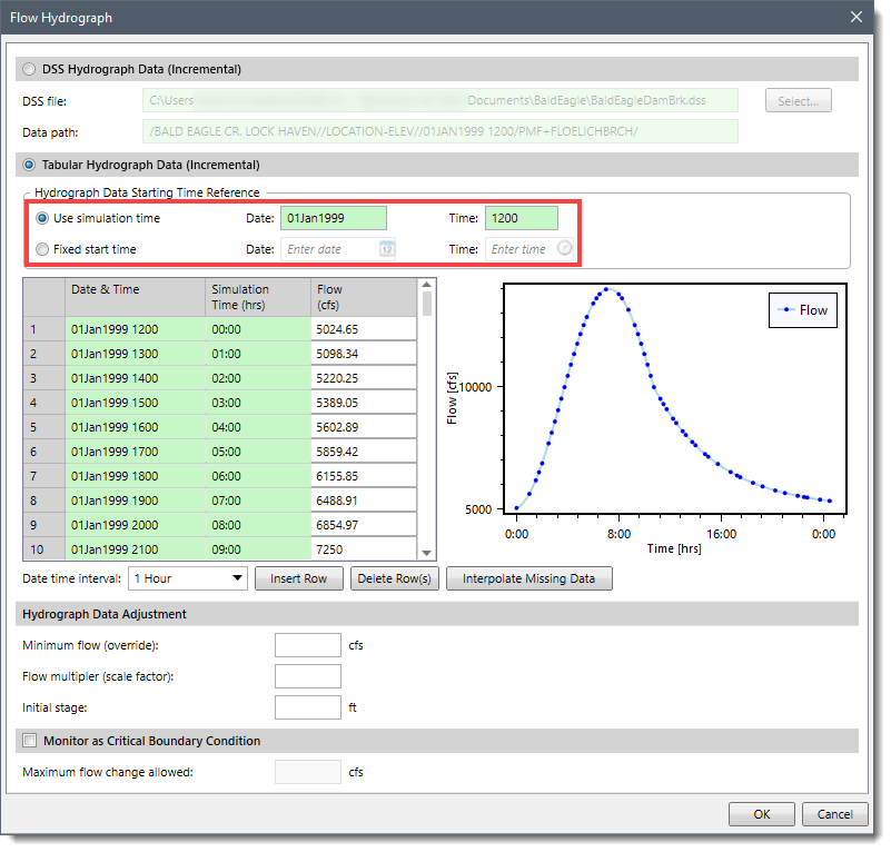
The Hydrograph Data Adjustment section at the bottom of the dialog box provides two options: Minimum flow (override) and Flow multiplier (scale factor). Both options apply to user-entered hydrographs or hydrographs read from HEC-DSS.
The Minimum flow (override) option allows the user to specify a minimum flow to be used in the hydrograph. This option is very useful when too low of a flow is causing stability problems. Rather than edit the user entered hydrograph or the DSS file (depending upon where the hydrograph is coming from), the user can enter a single value, and all values below this magnitude will be changed to that value. The Flow multiplier (scale factor) option allows the user to multiply every ordinate of the hydrograph by a user-specified factor.
Alternatively, the user can enable the Monitor as Critical Boundary Condition section at the bottom of the dialog box to make the selected boundary a Critical Boundary Condition. When this section is enabled, the software will monitor the inflow hydrograph to see if a change in flow rate from one time step to the next is exceeded. The user must enter a maximum allowed flow change value in the Maximum flow changes allowed input field. If the change in flow rate does exceed the user entered maximum value, the program will automatically cut the time step in half until the change in flow rate does not exceed the user-specified value. Large changes in flow can cause instabilities. The use of this feature can help to keep the solution of the model stable. This feature can be used for multiple hydrographs simultaneously. The software will initially evaluate all the hydrographs, then calculate a time slice based on the hydrograph with the largest percentage increase over the user-specified maximum flow change.
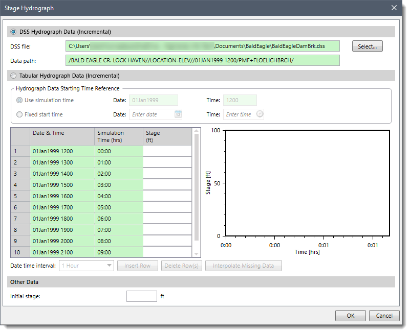
A stage hydrograph can be used as either an upstream or downstream boundary condition. The user can enter the boundary condition data for stage hydrograph boundary condition type in the Stage Hydrograph dialog box. Similar to the flow hydrograph boundary condition, the user has the choice of either attaching an HEC-DSS file and pathname or entering the data manually into a table.
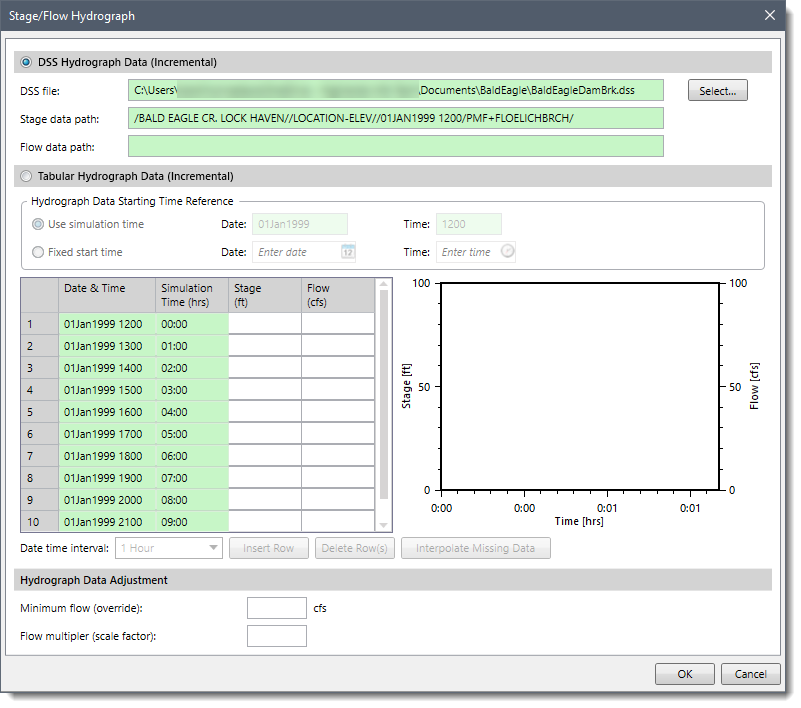
The stage and flow hydrograph can be used together as either an upstream or downstream boundary condition. The upstream stage and flow hydrograph is a mixed boundary condition where the stage hydrograph is inserted as the upstream boundary until the stage hydrograph runs out of data; at this point, the program automatically switches to using the flow hydrograph as the boundary condition. This type of boundary condition is primarily used for forecast models where the stage is observed data up to the time of the forecast, and the flow data is a forecasted hydrograph. The user can enter the boundary condition data for this boundary condition type in the Stage/Flow Hydrograph dialog box. The user has the choice of either attaching an HEC-DSS file and pathname or entering the data manually into a table.
The internal boundary stage and flow hydrograph (IB Stage/Flow) is an internal boundary condition that can be used at a cross section immediately upstream of an inline structure to force a known stage and/or flow for part or all of a simulation. It can also be used at an open cross section (one not associated with a hydraulic structure). For example, to force the water surface to match the water surface from known gage data, the boundary condition data for the internal boundary condition stage/flow hydrograph is entered in the Interior Boundary Stage/Flow dialog box. The user has the choice of either attaching an HEC-DSS file and pathname or entering the data manually into a table.
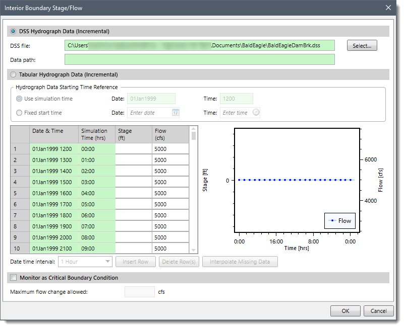
If the user enters only a stage hydrograph, then the program will force the stage at the cross section, and it will solve for the appropriate flow (to balance the unsteady continuity and momentum equations). Similarly, if the user enters only a flow hydrograph, then the program will force the flow at the cross section, and it will solve for the appropriate stage. The user may also enter both stage and flow data. As long as there is stage data, the software will force the stage (and solve for flow). When the stage data runs out, the software will begin to use the flow data (force the flow and solve for stage). This can often be useful when performing a forecast. Regardless of whether a stage and/or flow hydrograph is entered, if all the time series data runs out before the end of the simulation, then the program will treat the cross section as a regular cross section and will solve for both flow and stage in the normal manner.
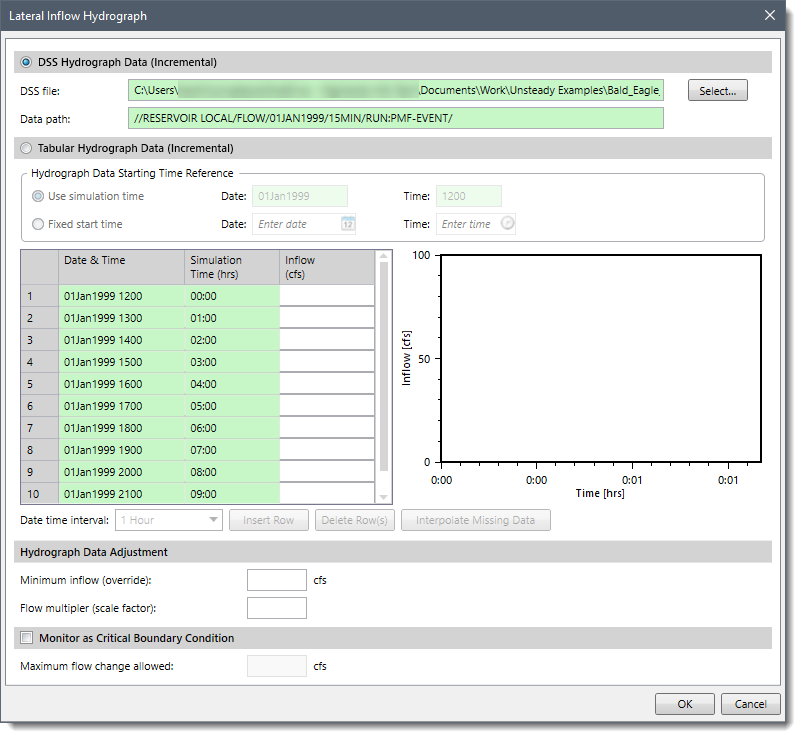
The lateral inflow hydrograph is used as an internal boundary condition. This boundary condition type allows the user to bring in flow at a specific point along the stream. The user attaches this boundary condition to the river station of the cross section just upstream of where the lateral inflow will come in. The actual change in flow will not show up until the next cross section downstream from this inflow hydrograph. The user can enter the boundary condition data for the lateral inflow hydrograph boundary condition type in the Lateral Inflow Hydrograph dialog box. The user can either read the hydrograph for this boundary condition type from the DSS file or enter it manually.
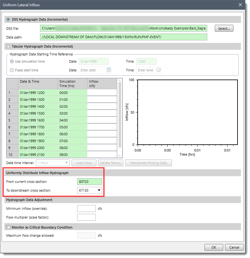
The uniform lateral inflow hydrograph is used as an internal boundary condition. This boundary condition allows the user to bring in a flow hydrograph and distribute it uniformly along the river reach between two user-specified cross section locations. The user can enter the boundary condition data for uniform lateral inflow hydrograph condition type in the Uniform Lateral Inflow dialog box. The hydrograph for this boundary condition type can be either read from a DSS file or entered manually into a table. The user can specify the two cross section locations where the flow hydrograph is to be distributed uniformly along the river reach in the Uniformly Distribute Inflow Hydrograph section.
The groundwater interflow boundary condition can be applied to a river reach or a storage area. Groundwater can flow into or out of a reach or storage area, depending on the water surface head. The stage of the groundwater reservoir is assumed to be independent of the interflow from the river and must be entered manually or read from DSS. The groundwater interflow is similar to a uniform lateral inflow in that the user enters an upstream and a downstream river station, in which the flow passes back and forth. The user can enter the boundary condition data for groundwater interflow boundary condition type in the Groundwater Interflow dialog box. The hydrograph for this boundary condition type can be either read from a DSS file or entered manually into a table.
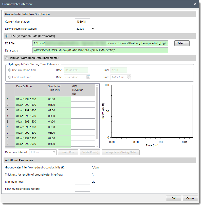
The groundwater interflow boundary condition can also be linked directly to a storage area for modeling groundwater exchange with ponding areas. The computed flow is proportional to the head between the river (or storage area) and the groundwater reservoir.
The computation of the interflow is based on Darcy’s equation. The user is required to enter the coefficient of permeability (Groundwater interflow hydraulic conductivity (K)), and the distance between the river and the location of the user entered groundwater aquifer stages (Thickness (or length) of groundwater interflow).
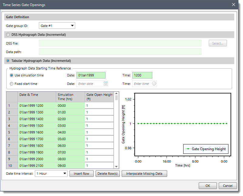
The time series (T.S.) gate openings boundary condition is probably the simplest gate boundary condition. The user simply enters a gate opening height for each time step of the entire simulation period. This boundary condition allows the user to enter a time series of gate openings for an inline gated spillway, lateral gated spillway, or a gated spillway connecting two storage areas. The boundary condition data for time series gate openings is entered in the Time Series Gate Openings dialog box. The user first needs to select a gate group and then read the data either from a DSS file or enter it manually. This is done for each of the gate groups contained within the hydraulic structure.
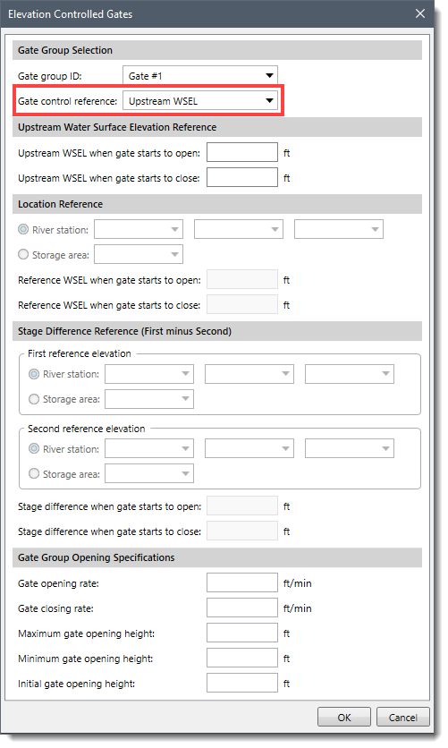
The elevation controlled gates boundary condition is a little more complicated. The user must tell the software when each gate will open and close as well as the opening and closing rates. Based on this information as well as the reference point, the software will decide what the gate setting should be at a particular time step. This boundary condition allows the user to control the opening and closing of gates based on the elevation of the water surface upstream of the structure (Upstream WSEL) or based on the water surface at a user-specified cross section or storage area (Location Reference) or based on a difference in water surface elevation from any two user-defined reference locations (Stage Difference). The boundary condition data for elevation controlled gates is entered in the Elevation Controlled Gates dialog box. In this dialog box, different sections for gate operating criteria are enabled based on the Gate control reference choice.
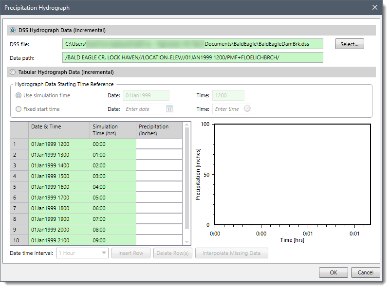
The precipitation boundary condition allows the user to enter a precipitation hydrograph between the cross sections, a storage area, or a 2D flow area. This boundary condition allows the user to enter incremental precipitation vs time data. The precipitation is used for the entire storage area or 2D flow area, with no spatial variability. The boundary condition data for precipitation is entered in the Precipitation Hydrograph dialog box. The hydrograph for this boundary condition type can be either read from a DSS file or entered manually into a table.


CivilGEO G2 Reviews
4.8/5.0 Rating, Over 230 Reviews

GeoHECRAS is recognized as the top Civil Engineering Design Software with an average of 4.8 out of 5.0 rating from over 230 real user reviews on G2.


We use cookies to give you the best online experience. By agreeing you accept the use of cookies in accordance with our cookie policy.
When you visit any web site, it may store or retrieve information on your browser, mostly in the form of cookies. Control your personal Cookie Services here.


