Automated Draw Cross Sections Command (HEC-RAS)
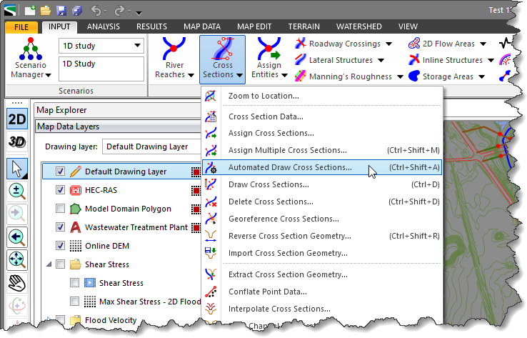
The Automated Draw Cross Sections command of GeoHECRAS software allows the user to automatically create cross sections along a river reach. The software will attempt to uniformly space cross sections along the river reach, creating cross sections that are perpendicular to the river reach. In places where adjoining cross sections might cross each other, the software will intelligently bisect the cross section point of intersection and then run the adjoining cross sections parallel to each other.
Follow the steps below to use the Automated Draw Cross Sections command in GeoHECRAS:
- From the Input ribbon menu, select the Cross Sections dropdown menu and then choose the Automated Draw Cross Sections command.
- The Automated Draw Cross Sections dialog box will be displayed.
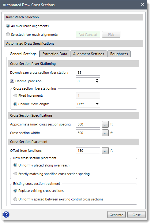
The following sections describe the Automated Draw Cross Sections command and how to interact with the above dialog box.
River Reach Selection
This section is used to select the river reach(es) that will be used to automatically draw cross sections. The following options are provided:
- All river reach alignments
This option causes all the defined river reaches within a model to have cross sections created along their respective reaches. This option works well when there is only one river reach in a model and the user wants the software to immediately start creating cross sections along its length. - Selected river reach alignments
This option is used to interactively select river reaches from the Map View for automatically drawing cross sections along the specified sections. Click the [Pick] button and the dialog box will temporarily disappear. A prompt will be displayed on the status bar, informing the user what to do next. Within the Map View, click on river reaches to select them. When finished selecting river reaches, right-click and choose Done from the displayed context menu or press the [Enter] key. The Automated Draw Cross Sections dialog box will be redisplayed, showing the number of river reach(es) selected.
Note that if river reach(es) have been preselected on the Map View before running this command, the number of selected river reach(es) will be displayed in the Selected river reach alignments read-only field.
General Settings
This tabbed panel is used to define the general settings for the cross sections to be created.
Cross Section River Stationing
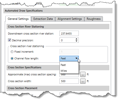
This section controls the numbering of the cross section river stations. The cross section river stations need to be unique per river reach and need to increase in value as they move up the river reach. The following entries are provided:
- Downstream cross section river station
This entry field allows the user to define the downstream most cross section river station for each selected reach and is used to determine the starting point for numbering the cross sections along the reach. When a single river reach is selected, this field displays the existing downstream cross section river stations (if cross sections already exist in the river reach). - Decimal precision
This checkbox controls whether the read-only spin control is enabled. The spin control allows the user to define the decimal precision used in determining the cross section river stations. By default, this check box is disabled (i.e., grayed out) and uses a value of 0. However, the user can enter a different value ranging from 0 to 6. - Cross section river stationing
This subsection is used to define how the cross section river stations are to increase in value as they move up the river reach. Two options are provided:- Fixed increment
This radio button option causes the cross section river stations to increase by a fixed value. - Channel flow length
This radio button option causes the cross section river stations to increase by an increment represented by the channel flow length from the previous (downstream) cross section river station. The user can select feet or miles as units of measure for computing the cross section river station as per the Channel flow length dropdown combo box.
- Fixed increment
Cross Section Specifications
This section is used to define the general specifications for the cross sections to be created. The following entries are provided:
- Approximate (max) cross section spacing
This field allows the user to define the maximum distance between cross sections when placing the cross sections. The software will attempt to uniformly space the cross sections along each river reach, up to this maximum spacing. This prevents the last cross sections created along a river reach from being spaced too close together. By default, the software uses a value of 500 feet or 150 meters. Clicking on the […] button allows the user to measure the approximate (max) cross section spacing from the Map View. - Cross section width
This field allows the user to define the cross section width to be used for extracting the cross section geometry from the terrain data. However, the defined cross section width is a starting point; additional criteria are provided to control how much data is to be extracted when the user extracts the ground geometry from the terrain. By default, the software uses a value of 500 feet or 150 meters. Clicking on the […] button allows the user to measure the cross section width from the Map View.
Note that the Cross section width field is ignored if the user has enabled the Cross Section Geometry Extraction Control section from the Extraction Data panel.
Cross Section Placement
This section is used to define the placement of the cross sections along the selected river reaches. The following entries are provided:
- Offset from junctions
This entry field is used to define the distance from a downstream and/or upstream junction(s) where cross sections should be located. This prevents a cross section from being placed directly at a junction. By default, the software uses a value of 150 feet or 50 meters. Clicking on the […] button allows the user to measure the offset distance from the Map View. - New cross section placement
This subsection is used to control how new cross sections should be placed. Two options are provided:- Uniformly placed along river reach
This radio button option is used to uniformly place new cross sections along the river reach depending on the cross section spacing specified in the Offset from junctions entry. - Exactly matching specified cross sections spacing
This radio button option is used to place new cross sections along the river reach at an exactly matching cross section spacing specified in the Offset from junctions entry.
- Uniformly placed along river reach
- Existing cross section treatment
This subsection is used to control how existing cross sections should be treated. Two options are provided:- Replace existing cross sections
This radio button option replaces any previously defined cross sections for the selected river reaches. - Uniformly spaced between existing control cross sections
This radio button option treats existing cross sections as control cross sections. Control cross sections are user-defined cross sections that are defined before the automated cross section creation process. These cross sections are typically placed at bridge and culvert roadway crossings, as well as at other important areas of interest where the automated cross section creation will not correctly locate the cross sections.
- Replace existing cross sections
Extraction Data
This tabbed panel is used to define the data extraction specifications and channel bank locations based upon the options selected for the cross sections to be created.
Extract Elevation Data
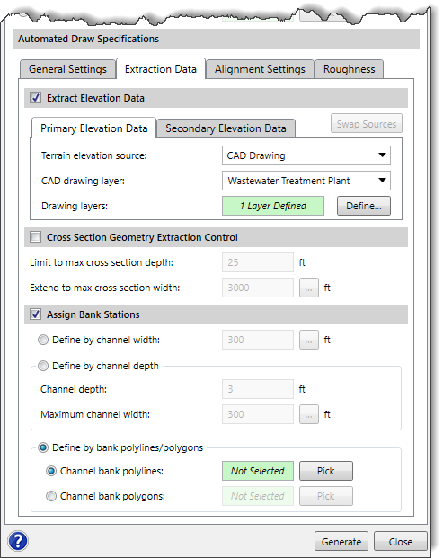
This optional section is used to define the elevation data source(s) to be used for extracting the cross section geometry. The user can use the Primary and Secondary Elevation Data panels to define the primary and secondary (if available in the project) elevation data sources for extracting the cross section geometry. Depending upon the elevation data source type that is selected, different options are provided to specify additional elevation data information.
Refer to this article in our knowledge base for information on the types of terrain elevation data that can be used for constructing cross sections.
The software will form a concave hull around the primary elevation data source to identify its bounds when a secondary elevation data source is available. For locations where elevation data from the primary data source is unavailable, the software will use the elevation data from the secondary data source.
Note that the user cannot utilize the same data source for defining both the primary and secondary elevation data.
The user can click the [Swap Sources] button to swap the selected elevation source from primary elevation data to secondary elevation data and vice versa.
If the Extract Elevation Data checkbox is unchecked, then the subsequent subsections and Cross Section Geometry Extraction Control section below it will be unavailable (i.e., grayed out). In addition, no geometry will be created when the cross sections are created. The cross sections will be just flat horizontal lines at elevation 0.
Cross Section Geometry Extraction Control
This optional section is used to control the amount of cross section geometry to extract for the automatically drawn cross section polylines. This assures that an adequately deep enough cross section is created on both sides of the river reach. The software will attempt to retrieve the cross section geometry data to the depth specified within the specified maximum cross section width.
If the drawn polyline does not extend outward far enough to get the cross section depth specified, the software will automatically extend the constructed cross section further outward. Similarly, if the drawn polyline extends too far outward for the depth specified, the software will automatically trim the constructed cross section.
Assign Bank Stations
This optional section is used to construct HEC‑RAS channel bank locations based on the selected option. The following options are provided:
- Define by channel width
This option will assign the bank stations using a defined channel width. The software will first determine the thalweg location on the cross section. It will then move outward from the thalweg equally until the requested channel width is reached. - Define by channel depth
This option will assign the bank stations using an assumed normal flow depth and a maximum channel width search distance. The software will first determine the thalweg location on the cross section. It will then move outward from the thalweg until the requested channel depth is reached within the maximum channel width specified. - Define by bank polylines/polygons
This option will assign the bank stations using selected polylines or polygons. Using the corresponding [Pick] buttons, the user can interactively select individual polylines or polygons on the Map View to be associated as bank stations. The user can click the [Clear] button to cancel the previous selection and redo the entire process.The software will first determine the thalweg location on the cross section. It will then move outward from the thalweg until a previously selected bank polyline or polygon edge is reached.
Alignment Settings
This tabbed panel is primarily used to perform automated cross section creation along sinuous (meandering) river reaches and is not used for other conditions. By default, the content of this panel is disabled (i.e., grayed out). In addition, no smoothing will be performed when the cross section is created. Select the Generalize Cross Section Alignment checkbox option to enable the content of this panel.
Generalize Cross Section Alignment
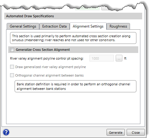
This checkbox option allows the user to control the river reach and cross section alignment smoothing and generalization. If this checkbox option is checked, the following options will be enabled to perform the cross section alignment smoothing:
- River valley alignment polyline control pt spacing
This entry field allows the user to enter the distance for smoothing river reach. Clicking on the […] button allows the user to measure the distance between spline control points for smoothing river reach from the Map View. - Draw generalized river valley alignment polyline
This checkbox option is used to draw the computed generalized river reach alignment polyline. - Orthogonal channel alignment between banks
This checkbox option is used to make the cross section orthogonal between the channel bank stations and generalized in the floodplain. Note that bank station definition is required to perform an orthogonal channel alignment between bank stations.
Assignment of Manning’s Roughness and Flow Lengths
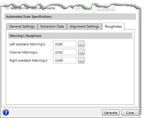
During the construction of the HEC‑RAS cross sections, the software will automatically assign a default Manning’s roughness for the left overbank, channel, and right overbank areas. The user can adjust these Manning’s roughness values in the Roughness tabbed panel.
In addition, the flow length to the next downstream cross section is determined. If inserting a new cross section between two adjacent cross sections, the software will automatically adjust the flow length of the next upstream cross section to account for the insertion of the new cross section.
Generating Cross Sections
When all the options have been properly defined in the Automated Draw Cross Sections dialog box, click the [Generate] button. The software will automatically generate the cross sections along a river reach.