
Welcome to CivilGEO Knowledge Base
Welcome to CivilGEO Knowledge Base
AutoCAD drawing files can be used as a terrain elevation data source in the following formats:
The following sections describe these elevation data sources in detail. Refer to this article in our knowledge base to learn how to add an AutoCAD drawing file as a data layer.
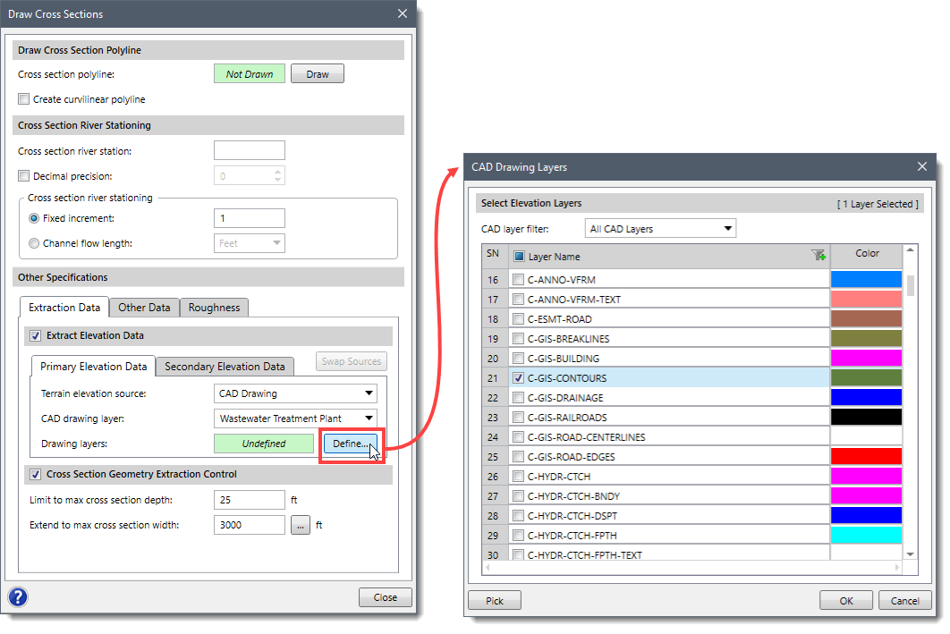
AutoCAD drawing files containing contour lines can be used to determine cross section geometry when cutting cross sections. In the Extract Elevation Data section contained within many of the create cross section dialog boxes, the user can select the AutoCAD layers containing contours for use in extracting cross sections.
AutoCAD drawing files containing contour lines can be used for generating a terrain surface for intersecting the computed water surface when determining the flood map and to determine cross section geometry when cutting cross sections. Refer to this article in our knowledge base to learn how to generate a terrain surface.
AutoCAD drawing files containing elevation point data can be used for generating a terrain surface for intersecting the computed water surface when determining the flood map and to determine cross section geometry when cutting cross sections.
The software can use AutoCAD Civil 3D, Bentley MicroStation, and other TIN surfaces to determine cross section geometry when cutting cross sections. TIN surfaces are imported as LandXML files.
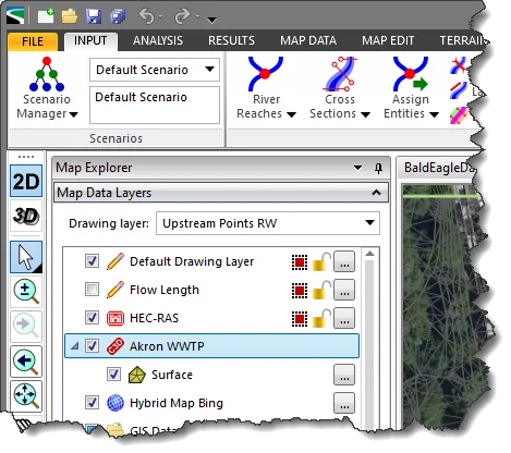
To load a LandXML terrain surface from within the Map Data Layers panel, right-click and select Add Layers from the displayed context menu. Then, select the corresponding LandXML TIN surface file to load. The TIN surface will be loaded and displayed as a layer.
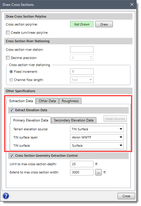
The LandXML surface can be used to determine the cross section geometry when cutting cross sections. In the Extract Elevation Data section contained within many of the create cross section dialog boxes, the user can select the TIN surface for use in extracting cross sections.
Currently the software cannot intersect the computed water surface directly with a TIN terrain surface. The user needs to generate a terrain surface from the TIN surface in order to generate a flood map.
†Civil 3D and Bentley MicroStation terrain surfaces imported as LandXML terrain models


CivilGEO G2 Reviews
4.8/5.0 Rating, Over 230 Reviews

GeoHECRAS is recognized as the top Civil Engineering Design Software with an average of 4.8 out of 5.0 rating from over 230 real user reviews on G2.


We use cookies to give you the best online experience. By agreeing you accept the use of cookies in accordance with our cookie policy.
When you visit any web site, it may store or retrieve information on your browser, mostly in the form of cookies. Control your personal Cookie Services here.


