
Welcome to CivilGEO Knowledge Base
Welcome to CivilGEO Knowledge Base
A flow area connection can be used to model a hydraulic structure between two adjacent storage areas, a storage area and 2D flow area, two adjacent 2D flow areas or within a single 2D flow area. The flow area connection within a single 2D flow area represents how an internal hydraulic structure allows flow to travel from one set of cells to another set of cells. For example, it can be used to model a roadway crossing in the middle of the 2D flow area, or similarly, represent a dam structure within the 2D flow area.
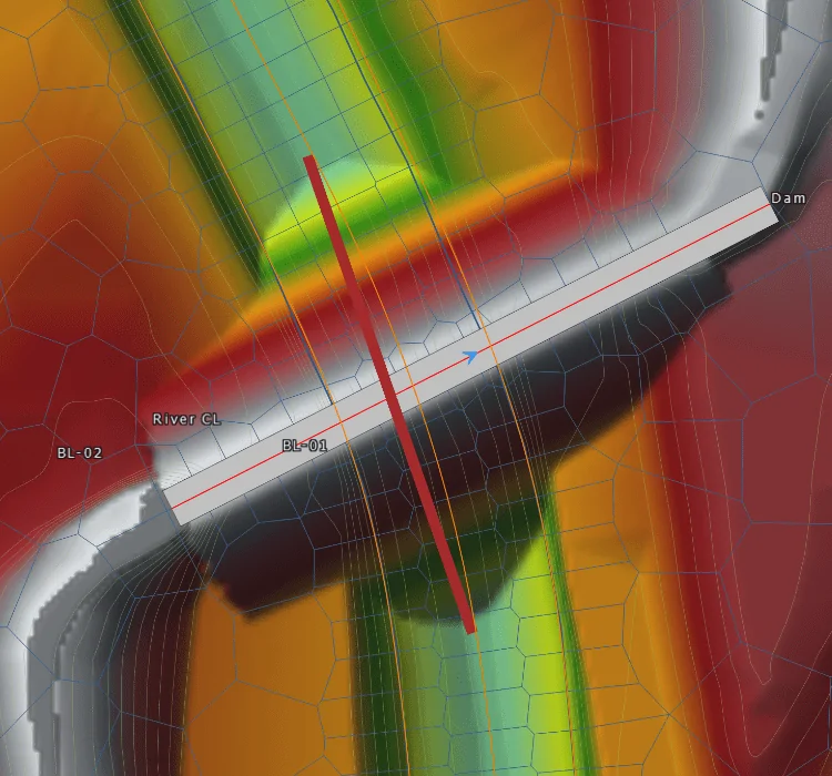
Example of a 2D flow area connection representing a dam structure with a culvert passing through it
For an internal 2D flow area connection, there should be a breakline that coincides with the 2D flow area connection alignment. Breaklines are used to force the alignment of the computational cell faces along barriers or other features that can significantly affect the 2D flow. GeoHECRAS software automatically verifies that the 2D mesh aligns with the connection element by automatically inserting a breakline coinciding with the 2D flow area connection alignment. This ensures that cell faces are aligned perpendicular to the flow going over the structure. This prevents flow from leaking through a structure if the 2D cell is large enough that it straddles both the upstream and downstream sides of the structure.
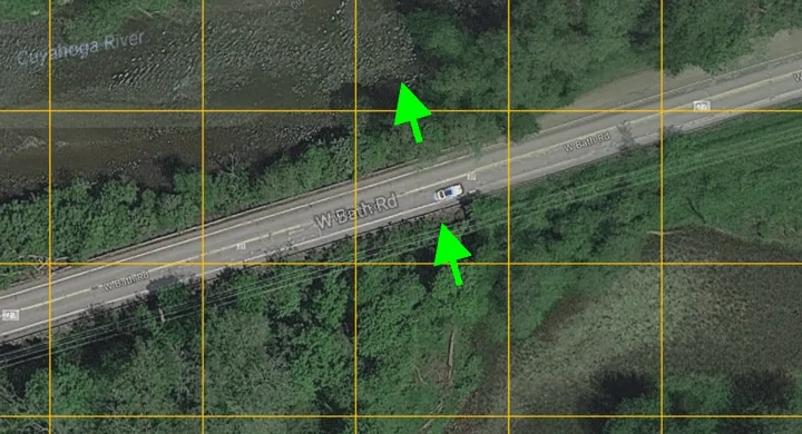
Example of 2D cell straddling element, causing flow to leak through the roadway crossing
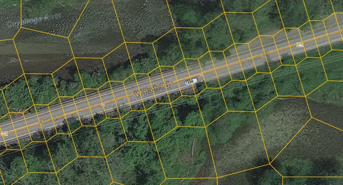
By aligning the cell faces with the structure, the leaking of flow is eliminated
If the 2D connection element starts or ends on a partial 2D flow area cell face, then the HEC-RAS preprocessor will report the following error message:
There is an error with the model data. The weir station/elevation extends too far beyond the last face point (face intersection).
This is shown below.
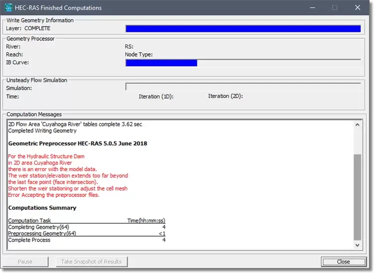
This situation occurs when the 2D connection element does not cover a majority of the 2D cell face. This can cause confusion for the computational engine, since it cannot determine if the flow should be through the 2D connection element or between cell faces. This is shown below.
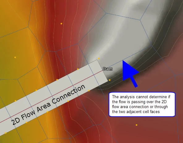
This 2D flow area connection will fail to run
By extending (or shortening) the 2D connection so that it occupies all (or most) of the cell face, the problem is resolved.
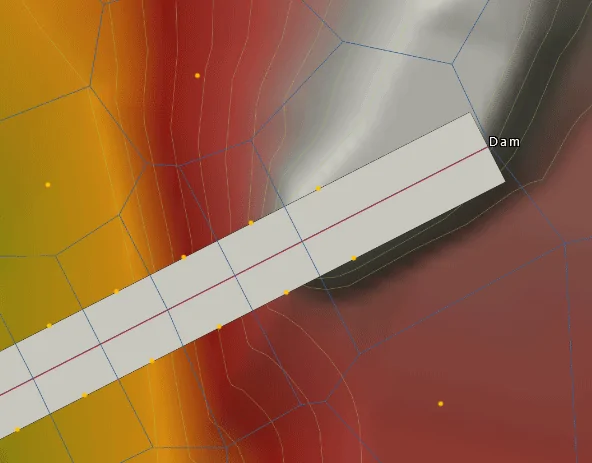
This 2D flow area connection will run
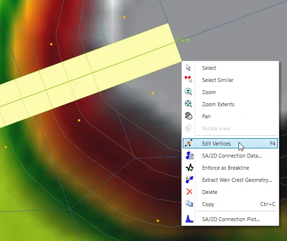
To edit the 2D flow area connection, select the element and then right-click and choose the Edit Vertices command from the displayed context menu (or press Function Key F4).
Next, grab the end vertex and resize the 2D connection so it covers the entire cell face.
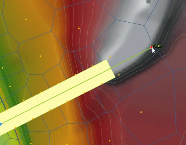
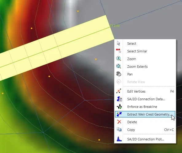
Then, right-click and choose Done from the context menu. Next, select the 2D connection and again right-click to display the context menu. Then, choose the Extract Weir Crest Geometry command.
The software will then display the Extract Weir Crest Geometry dialog box, allowing you to select the elevation data sources for extracting the weir crest geometry.
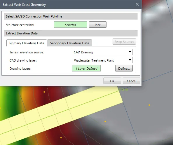
The Primary Elevation Data and Secondary Elevation Data panels are used to define the primary and secondary (if available in the project) elevation data sources for extracting the weir crest geometry. Depending on the selected elevation data source type, the content of these panels changes to specify additional elevation data information.
When a secondary elevation data source is available, the software forms a concave hull around the primary elevation data source. For locations where elevation data from the primary data source are unavailable, the software will use the elevation data from the secondary data source.
Note that the user cannot utilize the same data source for defining the primary and secondary elevation data.
The user can click the [Swap Sources] button to swap the selected elevation source from primary elevation data to secondary elevation data and vice versa.
After clicking the [OK] button, the software will then update the weir crest geometry to occupy the cell face.
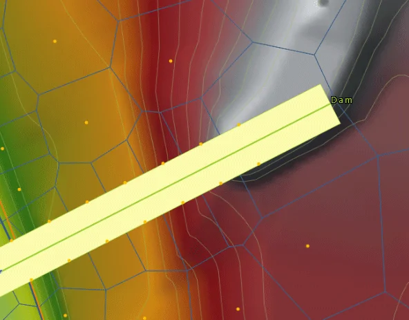
Now the model will run successfully.


CivilGEO G2 Reviews
4.8/5.0 Rating, Over 230 Reviews

GeoHECRAS is recognized as the top Civil Engineering Design Software with an average of 4.8 out of 5.0 rating from over 230 real user reviews on G2.


We use cookies to give you the best online experience. By agreeing you accept the use of cookies in accordance with our cookie policy.
When you visit any web site, it may store or retrieve information on your browser, mostly in the form of cookies. Control your personal Cookie Services here.


