
Welcome to CivilGEO Knowledge Base
Welcome to CivilGEO Knowledge Base
2D flow areas are regions of a model in which the flow through that region will be computed with the HEC-RAS two-dimensional flow computation algorithms. 2D flow areas are defined by laying out a polygon representing the outer boundary of the 2D flow area and then specifying the computational mesh. To learn more about 2D flow areas, refer to this article in our knowledge base.
In GeoHECRAS, the 2D flow area elements can be connected to 1D hydraulic elements in several ways, as described below:
2D flow areas can be used to model areas behind levees or overbank flow by connecting a 1D river reach to the 2D area using a lateral structure.
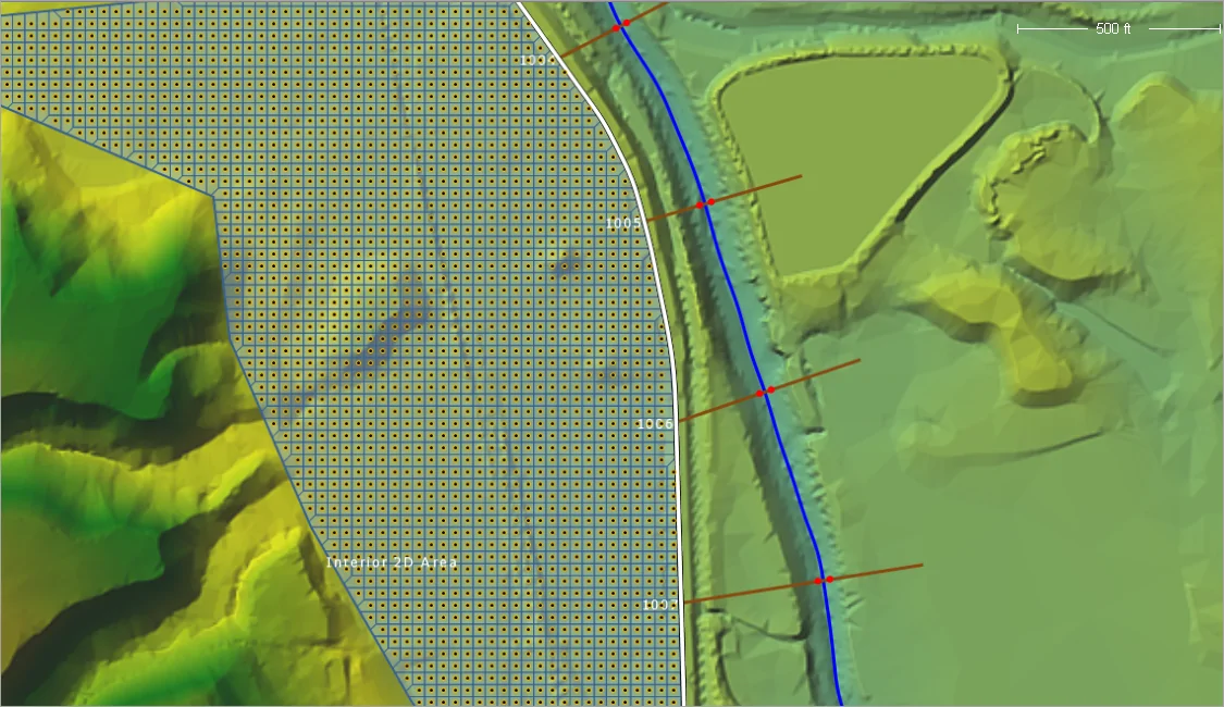
While adding lateral structure to the 1D river reach, the user can link it to another 1D river reach, a storage area, or a 2D flow area. If the user elects to link the lateral structure to a 2D flow area, in that case, the stationing of the lateral structure will be linked to the 2D area’s face points automatically (this is analogous to the lateral structure automatically determining the location and intersection of the 1D cross sections). To learn how to add a lateral structure to your model, refer to this article in our knowledge base.
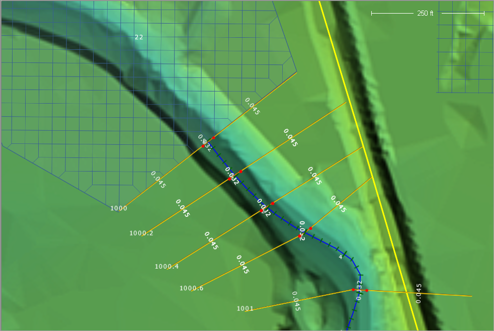
Once the lateral structure is drawn, the user can double-click on it in the Map View to display the Lateral Structure Data dialog box. The Overflow Weir data panel of this dialog box defines the top profile of the embankment as well as the lateral structure’s connection to the 1D river cross sections (the headwater side of the structure) and 2D area face points (the tailwater side of the structure).
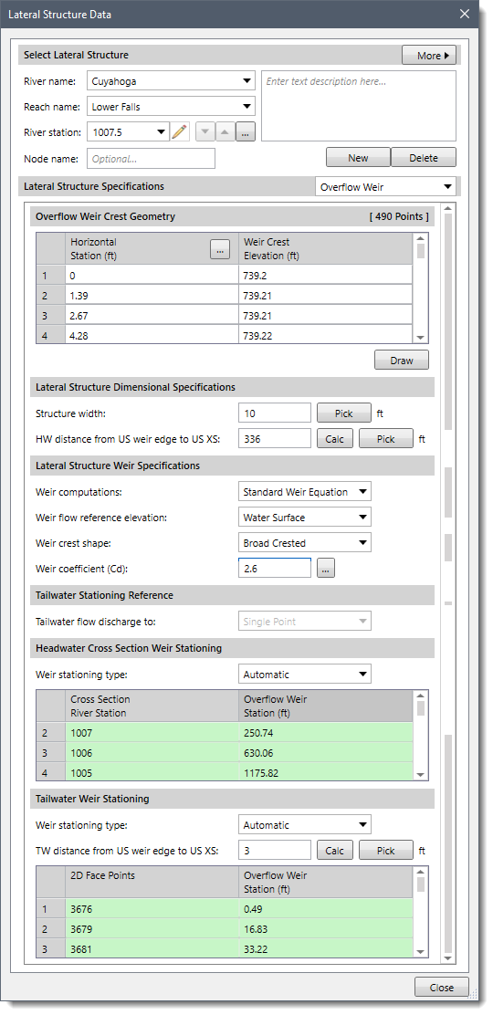
The first three sections in the data panel display the weir station and elevation points (Overflow Weir Crest Geometry), weir width (Structure width), headwater distance to upstream cross section (HW distance from US weir edge to US XS), and weir coefficient (Weir coefficient (Cd)). This defines the top profile of the lateral structure. The software automatically computes these values while adding lateral structure. However, the user can modify these values to whatever is desired.
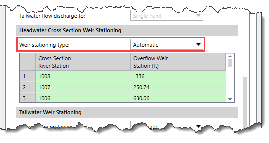
For the headwater (HW) connection to the 1D cross sections, the software automatically computes the intersection of the 1D cross sections with the lateral structure based on the cross section overbank reach lengths (or based on the lateral structures geospatial data) and the lateral structure weir profile stationing. The user can select the Manual Defined option from the Weir stationing type dropdown combo box to enter the user’s own intersection locations between the 1D cross sections and the lateral structure weir stationing.
For the tailwater connection to the 2D flow area, the software automatically computes the connection between the lateral structure weir stationing and the 2D flow area face points. The software finds the 2D flow area face points that start at the upstream end of the structure and go along the structure to the downstream end. Generally, a lateral structure will not start exactly at a 2D flow area face point. So, the software will pick the face point just upstream of the lateral structure to start the connection. This point will generally be given a negative weir stationing, meaning that it is upstream of the lateral structure by that distance. So, the zero weir stationing is actually in between two face points. The second face point in the table will be the next point downstream, and it will have a positive weir stationing. This stationing will represent how far the upstream end of the lateral weir is from that face point, along the length/stationing of the lateral weir. The user can choose the Manual Defined option from the Weir stationing type dropdown combo box to define the user’s own connection between the lateral structure weir station and the 2D flow area face points.
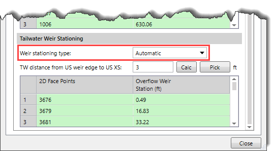
Note that the “Manual Defined” weir stationing is not available when the lateral structure is georeferenced.
Users can connect a 1D river reach directly to a 2D flow area. When this type of boundary condition is used, the last cross section of the 1D river reach must be lined up with the upstream boundary of the 2D flow area (i.e., the last cross section of the 1D reach is directly linked to the boundary of the 2D area, so they need to be at the exact same location).
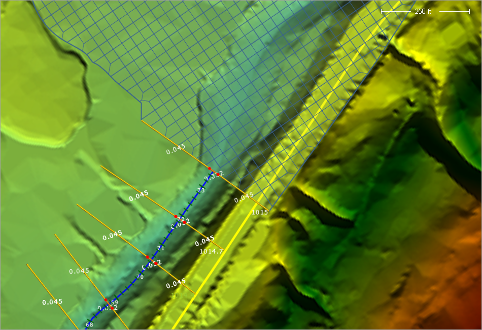
For this type of boundary condition, the 1D river reach passes flow each time step to the 2D flow area. The stage in the cross section is based on the water surface elevation in the 2D cells that it is connected to. Flow is distributed to the 2D cells based on the conveyance distribution in the cross section and the stationing of the cells linked to the cross section. The computed stage for the 1D cross section is based on computing a conveyance weighted stage from the connected boundary cells in the 2D flow area and then forcing that stage on the 1D cross section each time step.
Note that the connection between the 2D flow area and 1D river reach should only be placed in areas where the flow and stage are highly one-dimensional.
If the flow is not highly one-dimensional, the model can have stability issues. To overcome the stability issues, the user can turn on the Maximum iterations between 1D/2D interface option in the Unsteady Flow Computational Options dialog box.
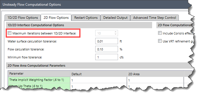
Enabling the Maximum iterations between 1D/2D interface option allows the software to iterate back and forth between the 1D and the 2D computations during each time step until the computed flow and stage at the boundary connection converges within a user-specified tolerance. However, this may not solve the issue for highly two-dimensional areas where the water surface varies significantly.
To learn how to turn on the Maximum iterations between 1D/2D interface option, refer to this article in our knowledge base.
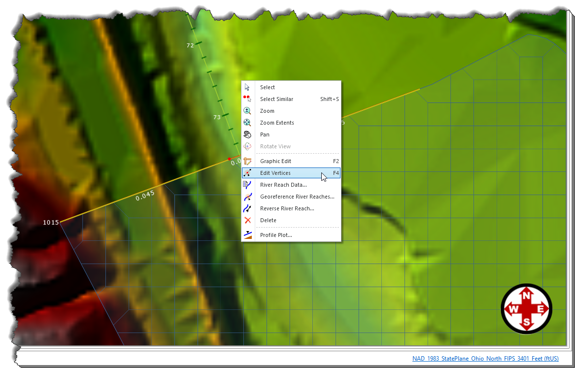
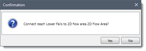
Follow the below steps to connect an upstream 1D river reach to a downstream 2D flow area:
This type of connection between a 1D cross section and a 2D area requires the following to be true:
Users can directly connect an upstream 2D flow area to a downstream 1D river reach. When this type of boundary condition is used, the first cross section of the 1D river reach must be lined up with the downstream boundary of the 2D flow area (i.e., the first cross section of the 1D reach is directly linked to the downstream boundary of the 2D area, so they need to be at the same exact location).
For this type of boundary condition, the 2D flow area passes flow each time step to the 1D river reach. The stage in the 2D flow area is based on the stage in the 1D cross section that it is connected to. Flow is passed to the 1D section by adding all of the flows leaving the 2D cells at the boundary for each time step. The stage for the 2D flow area downstream boundary is set to the computed stage of the 1D cross section each time step.
The procedure to connect an upstream 2D flow area directly to a downstream 1D river reach is similar to what was shown in the above section. Here, the only difference is that the user is required to draw the 2D flow area polygon such that the outer boundary at the downstream end is right on top of the first cross section of the 1D river reach.
This type of connection between a 1D cross section and a 2D area also requires the conditions mentioned in the previous section to be true.
A 2D flow area can be directly connected to a storage area using a hydraulic structure called a Storage Area/2D Flow Area Hydraulic Connector (SA/2D Area Connections).
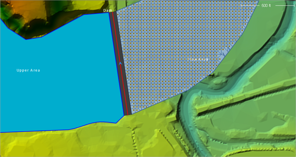
When defining the hydraulic structure that connects the two areas, the storage area will form the headwater side, and the 2D flow area will form the tailwater side. This can also be done the other way, in which the 2D flow area is on the upstream side (Headwater) and the storage area is on the downstream side (Tailwater).
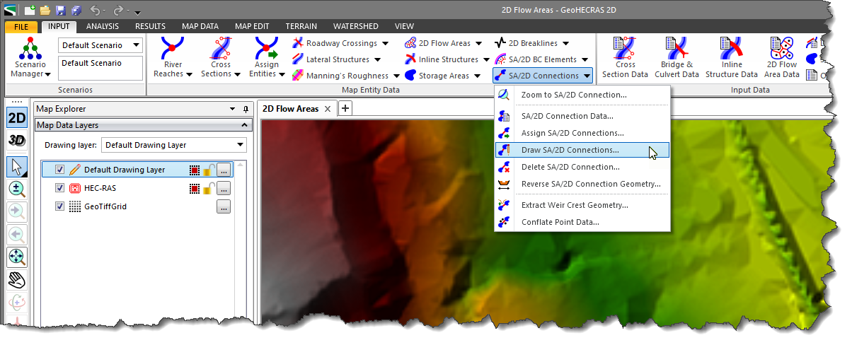
To hydraulically connect a storage area to a 2D flow area, follow these steps:
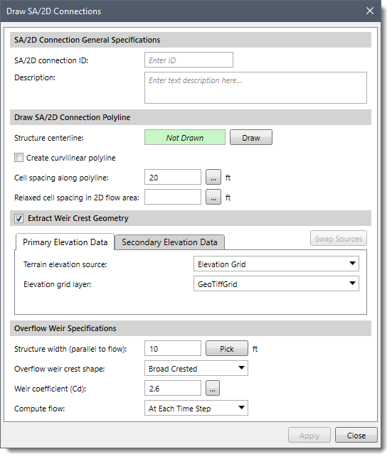
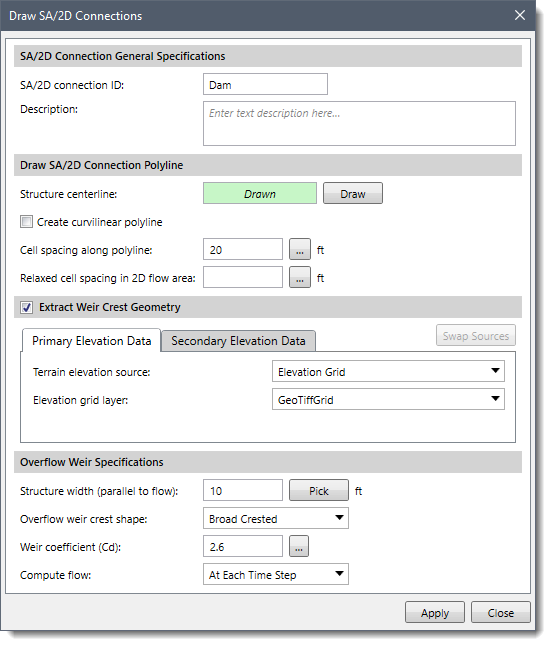
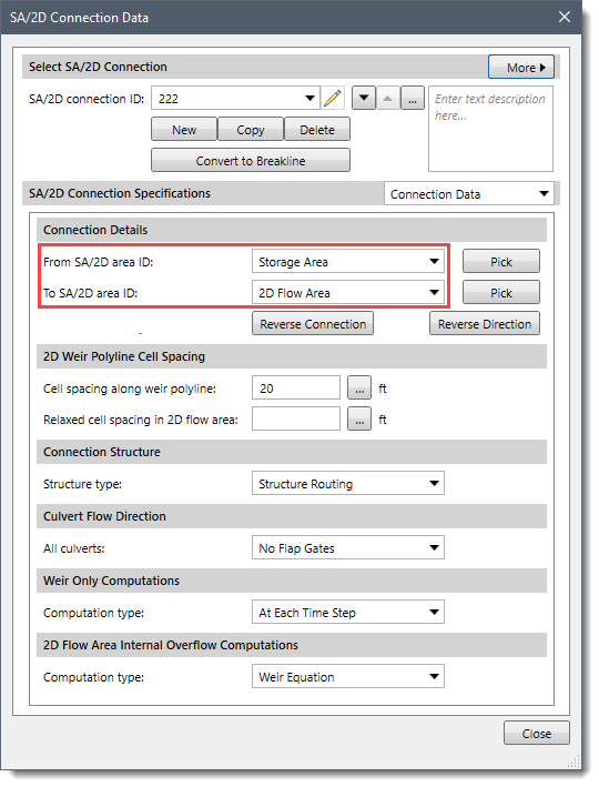
This is all that is needed for this type of hydraulic connection. GeoHECRAS will automatically compute the stationing along the centerline drawn for the hydraulic structure, and then line it up with the outer boundary of the 2D flow area based on its spatial location.
2D flow areas can also be directly connected to other 2D flow areas by using a hydraulic structure.
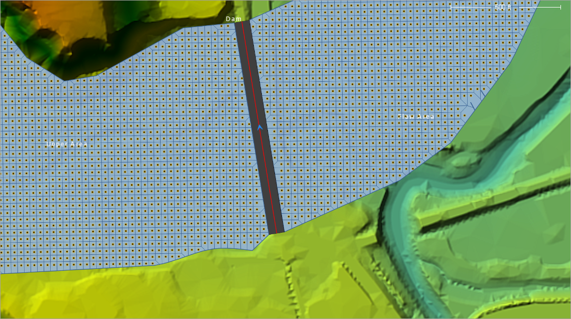
When defining the hydraulic structure that connects the two areas, the upstream 2D flow area will be considered the headwater side, and the downstream 2D flow area will be considered the tailwater side.
To hydraulically connect one 2D flow area to another, follow these steps:
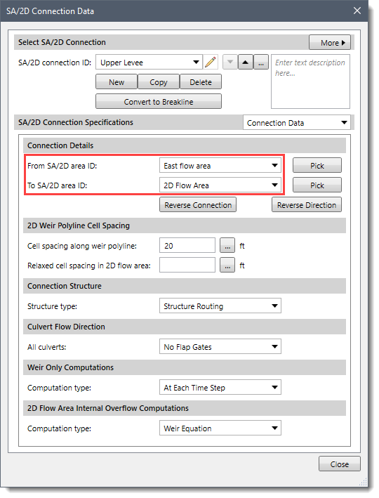
This is all that is needed for this type of hydraulic connection. GeoHECRAS will automatically figure out the stationing along the centerline drawn for the hydraulic structure, and then line it up with the outer boundary of the upstream and downstream 2D flow areas based on their spatial location.
GeoHECRAS can have any number (within the computer’s memory limitations) of separate 2D flow areas within the same geometry file. Multiple 2D flow areas can be added in the same way as storage areas. Hydraulic connections can be made from 2D flow areas to 1D elements and between 2D flow areas.


CivilGEO G2 Reviews
4.8/5.0 Rating, Over 230 Reviews

GeoHECRAS is recognized as the top Civil Engineering Design Software with an average of 4.8 out of 5.0 rating from over 230 real user reviews on G2.


We use cookies to give you the best online experience. By agreeing you accept the use of cookies in accordance with our cookie policy.
When you visit any web site, it may store or retrieve information on your browser, mostly in the form of cookies. Control your personal Cookie Services here.


